
Method for manufacturing printed circuit board using base material of high thermal conductivity suitable for being inserted into non-surface component

A printed circuit board, high thermal conductivity technology, applied in the direction of printed circuit, printed circuit manufacturing, printed circuit components, etc., can solve problems such as insulation loss

Inactive Publication Date: 2009-06-24
EUROCIR
View PDF0 Cites 5 Cited by
  • Summary
  • Abstract
  • Description
  • Claims
  • Application Information

AI Technical Summary

Problems solved by technology

[0011] The structure described above guarantees high heat dissipation, but it introduces a major limitation in the type of electronic components suitable for such printed circuits, of which surface mount devices (SMD) must be used, since the assembly of any kind of component that needs to be inserted necessarily causes Loss of insulation due to the electrical connection between the metal of the dissipative substrate and the conductive trace via the actual assembly (insertion pins), or due to the actual soldering process

Method used


Image

  • Method for manufacturing printed circuit board using base material of high thermal conductivity suitable for being inserted into non-surface component
  • Method for manufacturing printed circuit board using base material of high thermal conductivity suitable for being inserted into non-surface component
  • Method for manufacturing printed circuit board using base material of high thermal conductivity suitable for being inserted into non-surface component

Examples


Embodiment Construction

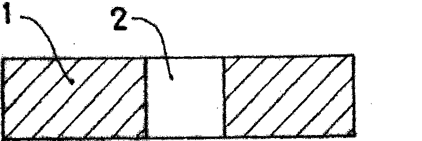
[0052] As can be seen in the figure, the procedure starts with the metal substrate (1) on which the embossing operation will be carried out, obtaining drilled holes (2) sufficient in number and position for the electronic components to be inserted later in the circuit. see figure 2 and 3 .

[0053] Next, the metal base plate (1) is deposited on a suction template (3) provided with appropriate suction holes (4) arranged correspondingly to the drilled holes (2). The injection head (5) of the printer with the injection hole (6) having the same diameter as the drilled hole (2) is located on the metal base (1). see Figure 4 .

[0054] The insulating resin (7) is then applied to the assembly under a certain pressure while evacuating air from the borehole (2) via the suction hole (4) until the borehole (2) is filled, as Figure 5 visible. Acrylate polymers obtained by exposure to ultraviolet light are advantageously used as insulating resins (7), more specifically Durashield ...


PUM


Abstract

The invention relates to a method for producing a printing circuit board by using a high heat conductivity substrate material suitable for inserting in a non-surface component comprising the following steps: molding a metal plate (1) to get a drilling (2) with enough number and position to insert in the surface component, arranging the metal substrate (1) on an aspiration formwork (3) which has an aspiration hole (4) corresponding to the drilling (2) so that an injection head (5) of a conventional printing machine falls on the metal substrate (1), filling an insulation resin (7) by an injection hole (6), simultaneously pumping the air from the drilling (2) by the aspiration hole (4), and molding the obtained component to get an insertion mould (12) with a diameter less than that of the corresponding initial drilling (2).

Description

technical field [0001] The present invention concerns the introduction of technical improvements based on the use of a metallic material (typically aluminum) as a physical support for a thin layer of metal (typically copper) on one of its faces in order to reinforce the use of highly thermally conductive materials (IMS) Functionality and efficacy of printed circuit boards. [0002] Such materials and printed circuit boards have been developed in response to the evolution of the requirements of the electronics industry related to new applications where operating temperatures are an issue due to the use of high heat-generating power components. [0003] The printed circuit boards obtained by the method of the invention can be advantageously used in a wide variety of applications where heat dissipation is a decisive factor, such as: [0004] — Lighting industry (LED circuit) [0005] - Automotive (ignition system, lighting, etc.) [0006] — solid state repeater [0007] - Dis...

Claims


Application Information

Patent Timeline
IPC IPC(8): H05K3/02H05K3/44H05K1/05
CPCH05K3/44H05K3/0047H05K3/125H05K3/1275H05K3/3452B23B41/14H05K2203/02
Inventor 胡安·龙格拉斯阿若拉
Owner EUROCIR
Learn More