Device for removing sulfuric dioxide in exhaust gas

A technology for sulfur dioxide and waste gas, which is applied in chemical instruments and methods, dispersed particle separation, separation methods, etc., can solve the problems of increased gas rising resistance, uneven gas distribution, and increased height of desulfurization towers, so as to increase the absorption rate and fully The effect of utilizing equipment space and promoting contact area

Active Publication Date: 2009-07-08
NINGBO JINYUANDONG PETROCHEM ENG TECH
View PDF1 Cites 17 Cited by
  • Summary
  • Abstract
  • Description
  • Claims
  • Application Information

AI Technical Summary

Problems solved by technology

But its disadvantages are: 1. The exhaust gas cooling is carried out in the absorption section of the gas-liquid separator in the absorption tower, that is, the exhaust gas is cooled by the water sprayed from the gas-liquid distributor or the countercurrent contact of the absorption liquid, and the cooling water It is added from the top of the desulfurization tower and mixed with the absorption liquid in the tower, resulting in: a. The absorption liquid is diluted; b. The temperature of the exhaust gas entering the desulfurization tower is higher. If it is to pass through the absorption liquid (or a mixture of water and absorption liquid) Countercurrent contact reduces the exhaust gas to a relatively low temperature, and can only increase the height of the desulfurization tower or increase the liquid-gas ratio
Both of the above two will lead to a decline in its absorption effect, or increase equipment investment and increase operating costs
2. The absorbing liquid distributor of this structure is a liquid sprayer, that is, the absorbing liquid is sprayed through the spray head, and the upwardly flowing gas flows upward through one side of the inner wall of the absorption tower. This structure is for the formation of gas-liquid Bias flow, so that the gas distribution is uneven, resulting in reduced contact area and low absorption rate; in addition, the gas-liquid separator rises due to the bias flow, which will increase the rising resistance of the gas and reduce the working efficiency

Method used


Image

  • Device for removing sulfuric dioxide in exhaust gas
  • Device for removing sulfuric dioxide in exhaust gas
  • Device for removing sulfuric dioxide in exhaust gas

Examples


Embodiment 1

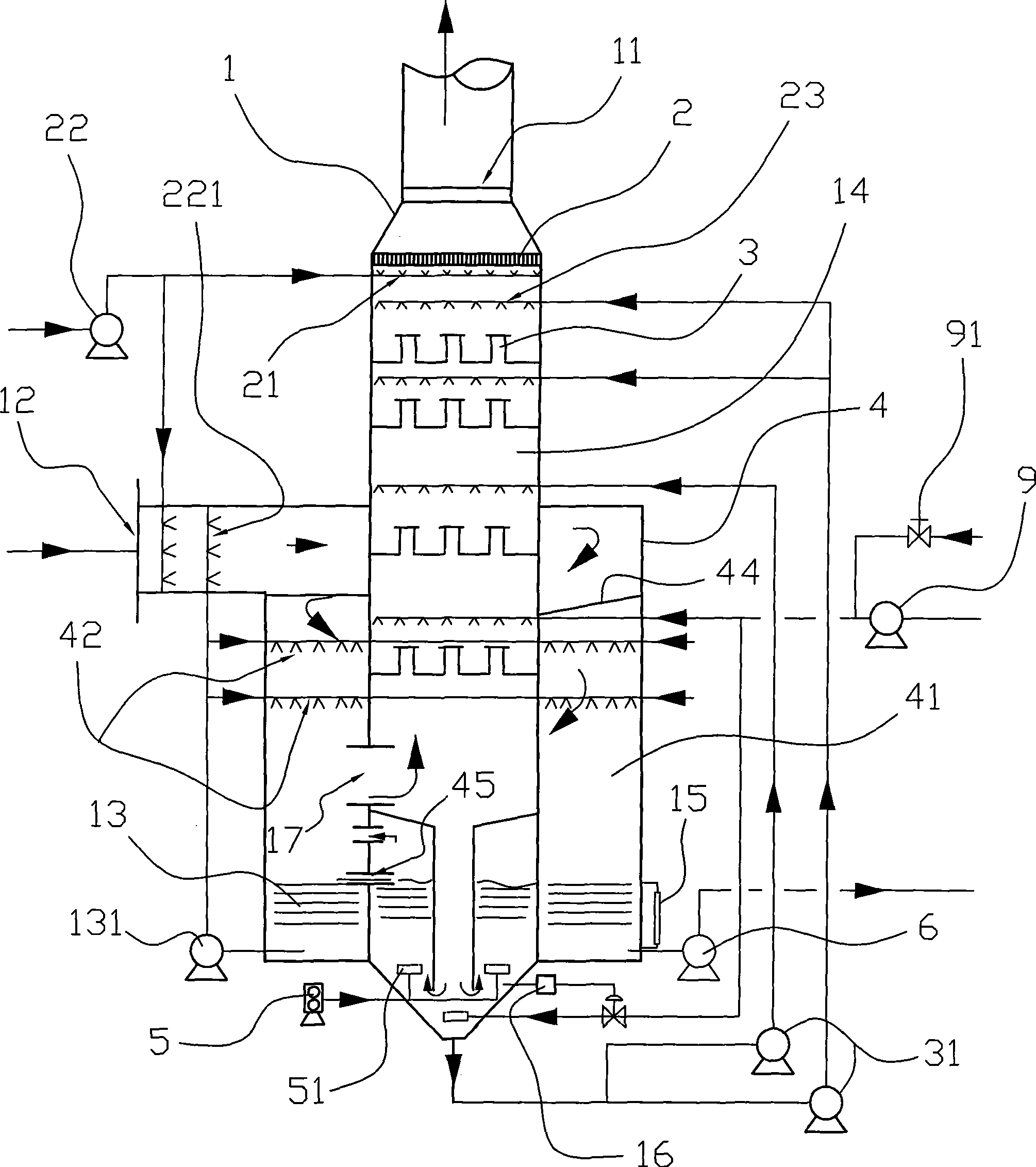
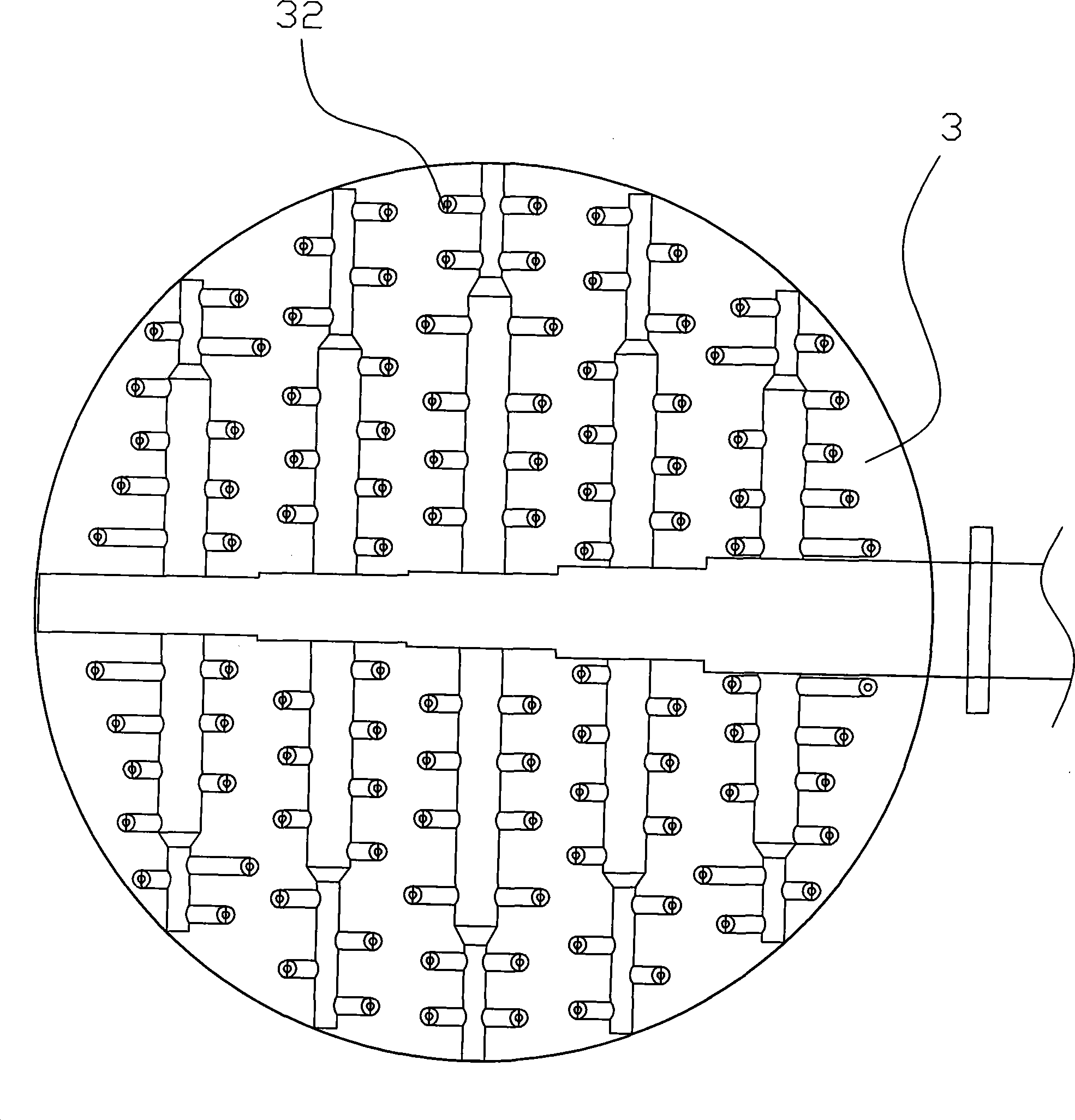
[0022] Embodiment one, such as figure 1 , Figure 3 to Figure 5As shown, the device for removing sulfur dioxide in the waste gas in this embodiment includes an absorption tower 1, a waste gas inlet 12 is arranged on the side of the middle part of the absorption tower 1, and a gas-liquid distributor 3 is arranged in the absorption tower 1, The top of the absorption tower 1 is provided with a clean gas discharge port 11, and the bottom of the absorption tower 1 is provided with an absorption liquid concentrated oxidation zone 13, and the concentrated oxidation zone 13 communicates with the air pipe provided with the air blower 5 in the outside through a pipeline, so that Oxidation in air can oxidize ammonium sulfite or ammonium bisulfite. The gas-liquid distributor 3 communicates with the absorption liquid in the concentrated oxidation zone 13 through a pipeline through a circulation pump 31 . The exhaust gas inlet 12 is connected with the cooling device in the absorption towe...

Embodiment 2

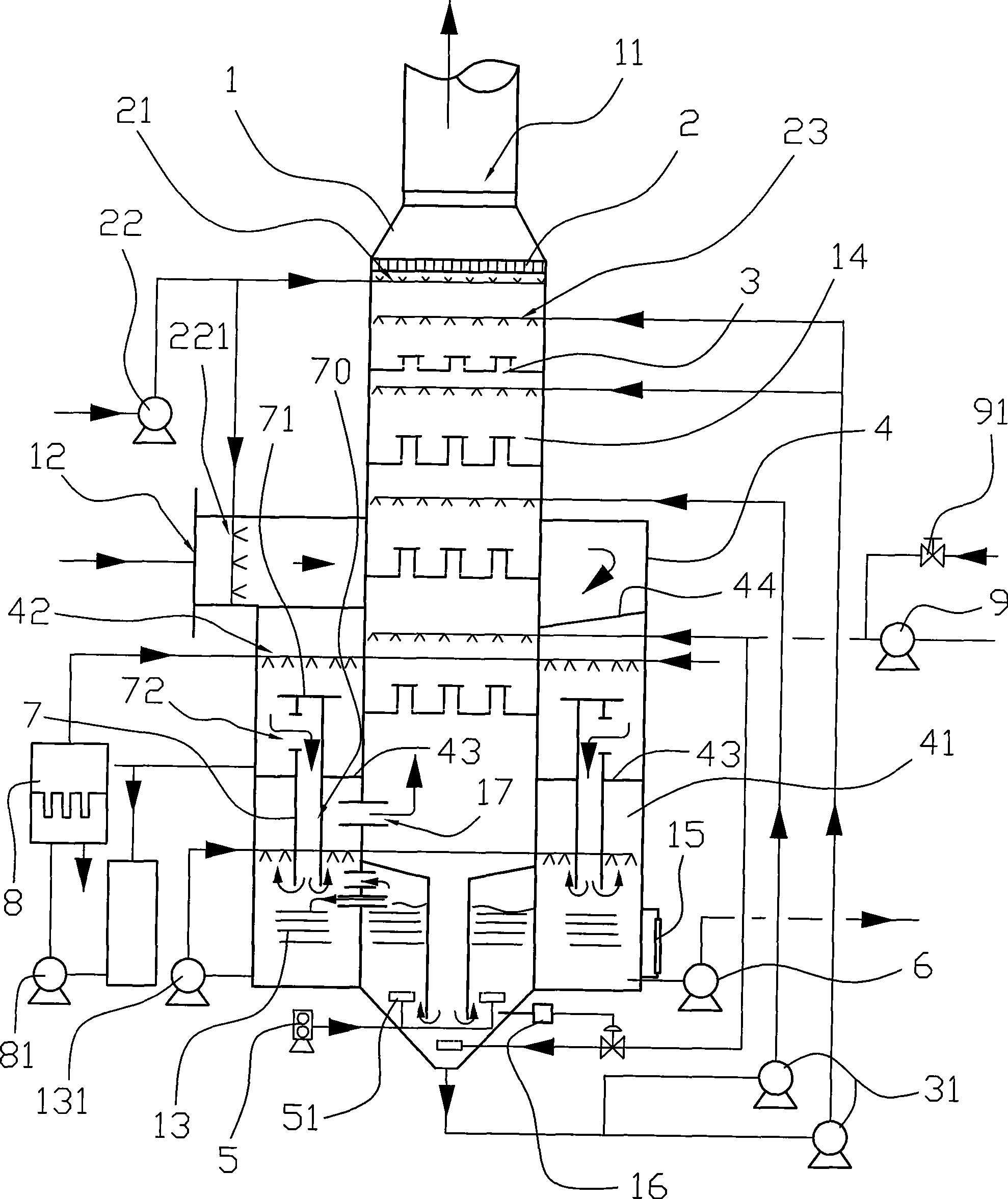
[0023] Embodiment two, such as figure 2 As shown, the basic structure of this embodiment is the same as that of Embodiment 1, the difference is that a dust removal mechanism is provided in the annular chamber 41, and the structure of the dust removal mechanism is: a vertically arranged annular Frame 7, the top of ring frame 7 is provided with the liquid baffle plate 71 that prevents liquid from entering ring frame cavity 70, has the inlet hole 72 that can make waste gas enter ring frame cavity 70 on the side that is positioned at ring frame 7, and ring The inner cavity 70 of the frame is connected with the concentrated oxidation zone 13, and a splint 43 is arranged in the annular cavity 41 to prevent the absorption liquid from entering the concentrated oxidation zone 13. The device 8 is connected, and the outlet of the absorption liquid filter 8 is connected with the sprayer 42 through a pipeline.

[0024] The present invention will be further described below.

[0025] The ...


PUM


Abstract

The invention relates to a device for removing sulfur dioxide in waste gases, which comprises an absorption tower (1). The side surface of the middle of the adsorption tower (1) is provided with a waste gas inlet port (12). The adsorption tower (1) is internally provided with a liquid-gas distributor (3). The top of the adsorption tower (1) is provided with a clean gas discharge outlet (11) while the lower part of the adsorption tower (1) is provided with an absorption liquid concentration oxidation zone (13). The device is characterized in that the waste gas inlet port (12) is communicated with a cooling device in the adsorption tower (1); the gas outlet of the cooling device is arranged below the liquid level of the absorption liquid of the concentration oxidation zone (13); the concentration oxidation zone (13) is communicated with the inner chamber of the adsorption tower (1). The device has the advantages that the waste gas cooling is carried out in the cooling device in the adsorption tower (1); the temperature of the gas in the inner chamber of the absorption tower is reduced into 45 DEG C to 60 DEG C; as the temperature is lower, the absorption effect is better after the gas and the liquid contact; therefore, when the gas with low temperature enters into the adsorption tower, the absorption rate is drastically increased; the device causes that processes such as waster gas, temperature reduction, concentration absorption liquid, desulphurization, oxidation and the like are concentrated in a desulfurizing tower to be completed, thus simplifying the low, reducing the equipment investment, fully making the best of device space and optimal land utilization.

Description

technical field [0001] The invention relates to a device for removing sulfur dioxide in waste gas. Background technique [0002] Usually, SO is contained in exhaust gas from mining industry, sulfuric acid industry, or coal-fired and oil-fired boilers. 2 gas. Even trace amounts of SO 2 Due to the huge amount of emissions, it will also cause serious damage to the environment and ecology. According to reports, my country has become the most severely affected area by acid rain after the Americas and Europe, and large tracts of forests and land have been destroyed. my country has clearly required that new power plants must be equipped with exhaust gas desulfurization devices, and that existing power plants with excessive emissions must install desulfurization facilities before the end of 2010. Those that have been in operation for more than 20 years or have an installed capacity of less than 100,000 kilowatts will be retrofitted or shut down within a time limit . At the same ...

Claims


Application Information

Patent Timeline
Patent Type & Authority Applications(China)
IPC IPC(8): B01D53/78B01D53/50
Inventor 项裕桥李顺保
Owner NINGBO JINYUANDONG PETROCHEM ENG TECH
Why Eureka
Try Eureka