
Detection piezoresistance and method for ultrathin silicon micromechanical cantilever beam under torsion mode

A technology of torsional mode and piezoresistive elements, which is applied in the measurement of the property force of piezoelectric resistance materials, piezoelectric effect/electrostrictive or magnetostrictive motors, electrical components, etc., can solve the problem that piezoresistive cannot be performed Photolithography to form graphics and other problems to achieve the effect of avoiding high-concentration shallow doping, wide application range, and simple structure

Active Publication Date: 2012-06-27
SHANGHAI INST OF MICROSYSTEM & INFORMATION TECH CHINESE ACAD OF SCI
View PDF0 Cites 2 Cited by
  • Summary
  • Abstract
  • Description
  • Claims
  • Application Information

AI Technical Summary

Problems solved by technology

For example: M.Gel et al once proposed in the article "Sub-micron thick high sensitive piezoresistive cantileverers byboron etch stop and argon implantation" (IEEE MEMS-03, Kyoto, Japan494-497, 2003) to use argon ion implantation on the back to form front pressure Although the thinner piezoresistive sensitive element can be made in a certain depth range, the thinnest cantilever beam is only 0.4 micron; while Kenny et al. thick" (Appl.Phys.Lett.75289-291, 1999), the piezoresistive cantilever sensor with a thickness of 100 nanometers produced by epitaxial technology also has the disadvantage that the piezoresistive cannot be photolithographically formed. In addition, Due to the unavoidable thermal diffusion of ions in the subsequent thermal annealing process, the thickness of the cantilever beam is difficult to be thinner

Method used


Image

  • Detection piezoresistance and method for ultrathin silicon micromechanical cantilever beam under torsion mode
  • Detection piezoresistance and method for ultrathin silicon micromechanical cantilever beam under torsion mode
  • Detection piezoresistance and method for ultrathin silicon micromechanical cantilever beam under torsion mode

Examples


Embodiment Construction

[0039] The piezoresistive detection method of the ultra-thin silicon micromechanical cantilever beam resonator provided by the present invention is further explained by specific examples to express the essential features and significant progress of the present invention. However, the present invention is by no means limited to the embodiments.

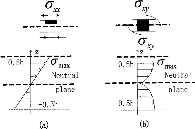
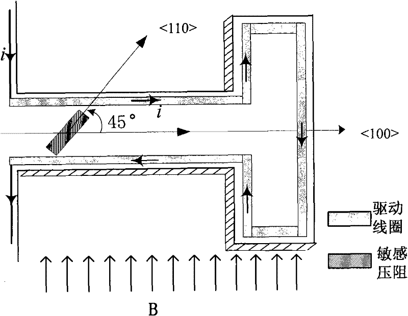
[0040] Taking a first-order torsion mode silicon micromachined piezoresistive cantilever beam resonator as an example, the effect and implementation of this piezoresistive detection method are explained in detail. The basic working principle of this type of piezoresistive resonator is as follows: the cantilever beam will undergo torsional vibration under a certain driving force. When the frequency of the driving force is the same as the resonance frequency of the first-order torsional mode of the cantilever beam, the cantilever beam will generate a first-order The torsion mode resonance, the sensitive piezoresistance converts the shear st...


PUM

PropertyMeasurementUnit
thicknessaaaaaaaaaa
thicknessaaaaaaaaaa

Abstract

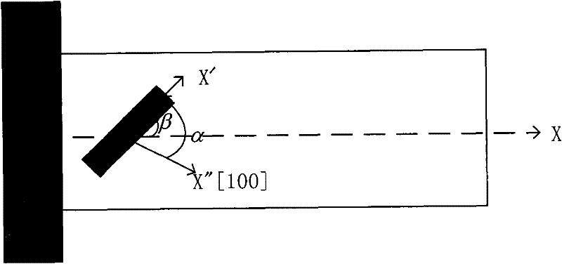
The invention relates to a detection piezoresistor for an ultrathin silicon micromechanical cantilever beam under a torsional mode and a method for detecting the piezoresistor, and belongs to the technical field of micromechanical sensing. The method is specifically characterized in that the method uses shear stress distribution characteristics of the micromechanical cantilever beam under the torsional mode to penetrate a piezoresistive doped region for signal detection to the thickness of the whole silicon cantilever beam, thereby breaking through the limit that the piezoresistive sensing region of the micromechanical cantilever beam cannot overpass half of the beam thickness under the prior bending mode; and the method simultaneously combines anisotropy of silicon piezoresistive coefficient and distribution characteristic of stress tensor on the cantilever beam to optimally design the arrangement direction of the cantilever beam and the piezoresistor, so that the relative variable of the piezoresistor reaches the maximum, and the mechanical property of the cantilever beam is improved. The piezoresistor and the method have the advantages of simple structure, convenient manufacture and easy realization.

Description

Technical field [0001] The invention relates to a piezoresistance detection and a piezoresistance detection method suitable for ultra-thin silicon micromechanical cantilever beams working in a torsion mode. More precisely, the present invention uses ordinary ion doping technology to produce a sensitive piezoresistance through the thickness of the thin beam, and converts the shear stress in the torsional mode micromechanical cantilever beam into an electrical signal to detect ultra-thin silicon micro Vibration of a mechanical cantilever beam. The invention belongs to the field of micro-nano electromechanical systems. Background technique [0002] Piezoresistive silicon micro-cantilever sensors have been widely used in the fields of bioimaging technology, pressure sensitivity and biochemical trace detection in recent years due to their simple structure, easy integration, and extremely high sensitivity to force and quality. The core component of this type of sensor is the silicon ...

Claims


Application Information

Patent Timeline
Patent Type & Authority Patents(China)
IPC IPC(8): B81C5/00B81B7/02G01H11/08G01L1/18B81C99/00
Inventor 李昕欣夏晓媛
Owner SHANGHAI INST OF MICROSYSTEM & INFORMATION TECH CHINESE ACAD OF SCI
Learn More