Manufacturing process of wind-power principal shaft product and its special integral forming device

A wind power spindle and integral forming technology, applied in the direction of final product manufacturing, sustainable manufacturing/processing, wind power generation, etc., can solve the problems of increasing machining cost, affecting machining efficiency, increasing flange forging allowance, etc., and achieve saving Machining man-hours, improving the pass rate of flaw detection, and reducing the effect of forging fire times

Inactive Publication Date: 2009-07-08
武汉重工铸锻有限责任公司
View PDF2 Cites 8 Cited by
  • Summary
  • Abstract
  • Description
  • Claims
  • Application Information

AI Technical Summary

Problems solved by technology

Due to the large flange and small diameter of the shaft body, the rough flange and the shaft body are prone to eccentricity, often resulting in insufficient machining allowance and scrapping of the product
In order to meet the processing needs, it is necessary to increase the forging allowance of the flange, and accumulate a large amount of process auxiliary materials at the transition part between the flange and the shaft body, so that

Method used


Image

  • Manufacturing process of wind-power principal shaft product and its special integral forming device
  • Manufacturing process of wind-power principal shaft product and its special integral forming device
  • Manufacturing process of wind-power principal shaft product and its special integral forming device

Examples


Embodiment Construction

[0029] Describe the present invention in detail below with reference to accompanying drawing:

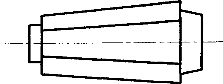
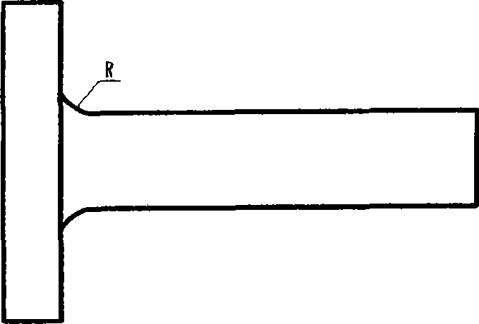
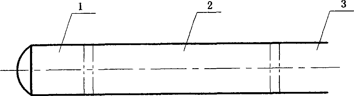
[0030] The present invention selects 42CrMo, 42CrMo4 or 34CrNiMoA alloy steel, and is smelted into figure 1 After the steel ingot 1 of the shape shown is sent to the forging workshop, it is heated to the forging temperature for upsetting, and the upsetting becomes figure 2 The T-shape 2 shown has a transition arc 3 in the T-shape 2 . Then carry out the elongating operation, and elongate into a blank of a certain size (see image 3 ), the bottom scrap 4 and the riser scrap 6 are cut by oxygen to obtain the forging blank 5. continue to elongate Figure 4 In the shown shaft body, the diameter φD / φd of the large and small steps 7 and 8 of the shaft body blank is 1.25-1.45, so as to facilitate integral forging of the flange.

[0031] refer to Figure 5 , the integral special molding device for the production of integral wind power main shaft products has an upper flange cavity 9 in...


PUM


Abstract

The invention relates to a manufacturing process for a wind power main shaft product and a special one-piece forming device thereof. The invention relates to a method for manufacturing a wind power main shaft product and a one-piece forming device thereof. The manufacturing process comprises the following steps: carrying out the ladle refining of molten steel, then pouring the molten steel to form an ingot, carrying out the hot delivery and heating the ingot to reach a forging temperature, upsetting and drawing out the ingot, cutting off a casting head and discarded bottom material, forging the ingot into a bench shaft-shaped blank, designing the special forming device with allowance, lifting the blank into the special forming device, integrally forming a flange, carrying out the finishing and shaping the parts of the forged piece, carrying out the heat treatment after forging, the rough machining, the semi-finishing and the finishing, and obtaining the product. The manufacturing process adopts the steps of upsetting and drawing out the ingot, and forging and forming the flange through the special one-piece forming device so as to ensure that the forging ratio at the flange part reaches above 3.0. The manufacturing process can greatly improve the flaw detection passing percent of the flange, guarantee the intrinsic quality of the product, and have few forging times, low cost and few work hours. 1,000 wind power main shafts between 0.70 and 1.50MW are manufactured by the invention. The long-period practice verifies that the manufactured wind power main shafts have reliable intrinsic quality and stable outline quality.

Description

technical field [0001] The invention relates to a method for manufacturing wind power main shaft products and an integral forming device. Background technique [0002] At present, the domestic and international wind power generation markets are huge, and one of the most critical components in wind power generators - the wind power main shaft, is in short supply. The product is characterized by large flange, small shaft diameter, difficult molding, and high technical requirements. Due to the large flange and small diameter of the shaft body, the rough flange and the shaft body are prone to eccentricity, which often results in insufficient machining allowance and scrapping of the product. In order to meet the processing needs, it is necessary to increase the forging allowance of the flange, and accumulate a large amount of process auxiliary materials at the transition part between the flange and the shaft body, so that the utilization rate of the material is low, which not on...

Claims


Application Information

Patent Timeline
IPC IPC(8): F03D1/06F03D11/00F16C3/02
CPCY02E10/721Y02E10/72Y02P70/50
Inventor 刘志勇刘长安黄丽秋张承峰周德祥彭茂华熊武刘振新刘秀环金迎松
Owner 武汉重工铸锻有限责任公司
Why Eureka
Try Eureka