Optical system used for focusing and leveling

An optical system, focusing and leveling technology, which is applied in the field of focusing and leveling optical systems, can solve the problems of increasing the size of key parts, large reflection loss, and small working distance, so as to reduce design difficulty, reduce reflection loss, expand The effect of working distance

Active Publication Date: 2009-07-08
SHANGHAI MICRO ELECTRONICS EQUIP (GRP) CO LTD
View PDF2 Cites 19 Cited by
  • Summary
  • Abstract
  • Description
  • Claims
  • Application Information

AI Technical Summary

Problems solved by technology

Because the aperture and numerical aperture of the objective lens in the lithography machine are both large and its working distance is very small, this leads to a large projection angle of the focusing subsystem, that is, the incident angle of each object image plane is very large, and the angle on each oblique mark The reflection loss is very large, which reduces the sensitivity of the system; at the same time, the focal length requirements of the ordinary double-telecentric system are also increased, which increases the size of key components (such as scanning mirrors)
In order to ...

Method used


Image

  • Optical system used for focusing and leveling
  • Optical system used for focusing and leveling
  • Optical system used for focusing and leveling

Examples


Embodiment Construction

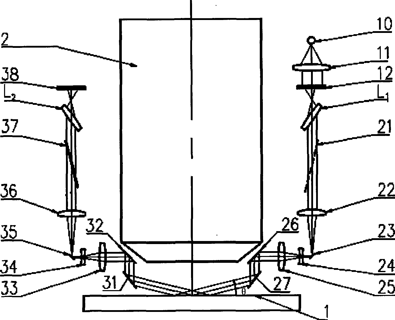
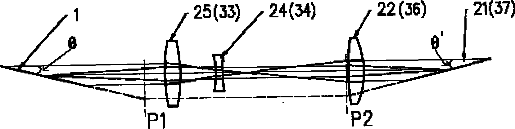
[0013] The optical structure of the present invention is composed of an illumination unit, a marking plate, an oblique imaging unit, a projection imaging unit, a receiving imaging unit, a correcting imaging unit and a detector. The illumination unit provides evenly illuminated broadband light, which illuminates the marking plate, and the marking plate forms an inclined marking image through the inclined imaging unit, and the inclined marking image is imaged on the surface of the silicon wafer by the projection imaging unit, and is received The imaging unit images the receiving mark, and then corrects the imaging unit to image the image on the detector. The position change of the silicon wafer will cause the position change of the receiving marker, so as to achieve the purpose of detecting the position of the silicon wafer.

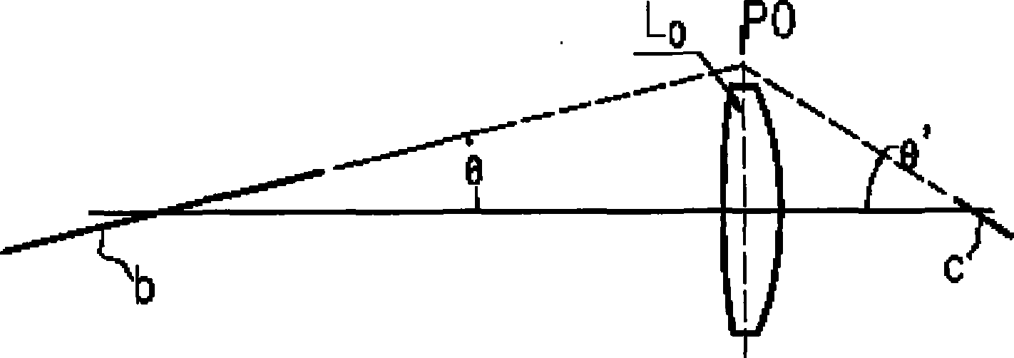
[0014] The structure of the above oblique imaging unit, projection and receiving imaging unit and correction imaging unit all satisfy the Scheimpflug condi...


PUM


Abstract

The invention discloses an optical system for focusing and leveling, which comprises an illumination unit, a marking plate, an oblique imaging unit, a projection imaging unit, an accept imaging unit, a correction imaging unit and a detector, wherein the illumination unit provides broadband light for uniform illumination and illuminates the marking plate; the marking plate forms an oblique mark image through the oblique imaging unit; the oblique mark image is imaged on a silicon slice surface by the projection imaging unit and reflected by the silicon slice surface, and forms an accept mark through the accept imaging unit; and the accept mark is transmitted to the detector through the correction imaging unit. The novel proposal for the focusing and leveling system provided on the basis of Scheimpflug condition comprises that: a vertical plane is changed into an oblique plane in an imaging mode so as to reduce reflection loss and design difficulty. Simultaneously, the aim of reducing the focal length and increasing the operating distance is achieved by adoption of a telephoto structure on a near measuring plane of a telecentric optical system.

Description

technical field [0001] The invention relates to an automatic focusing control system of projection exposure equipment, in particular to an optical system for focusing and leveling. Background technique [0002] A projection lithography machine is a device that projects a pattern on a mask onto a silicon wafer through an objective lens. In the projection exposure equipment, there must be an automatic focus control system to accurately bring the silicon wafer to the designated exposure position, and there are many different technical solutions for realizing this system. At present, the non-contact photoelectric measurement technology is more commonly used, among which the focusing technology of NIKON, CANON, and ASML is the most representative. The schemes of the above companies have their own characteristics. What they have in common is that the optical part of the measurement system adopts an optical structure that satisfies the Scheimpflug condition (that is, the condition...

Claims


Application Information

Patent Timeline
IPC IPC(8): G03F9/00G03F7/20
Inventor 张冲徐兵李志丹
Owner SHANGHAI MICRO ELECTRONICS EQUIP (GRP) CO LTD
Why Eureka
Try Eureka