
Light emitting diode apparatus having heat conductive substrate

A technology of light-emitting diodes and bases, which is applied to semiconductor devices, semiconductor/solid-state device components, electrical components, etc., can solve problems such as component failure, lattice defects, and complicated manufacturing processes, and achieve conductive processing problems, long and The effect of stable working life and high light output efficiency

Inactive Publication Date: 2011-04-06
CHI MEI LIGHTING TECHNOLOGY CORP
View PDF5 Cites 0 Cited by
  • Summary
  • Abstract
  • Description
  • Claims
  • Application Information

AI Technical Summary

Problems solved by technology

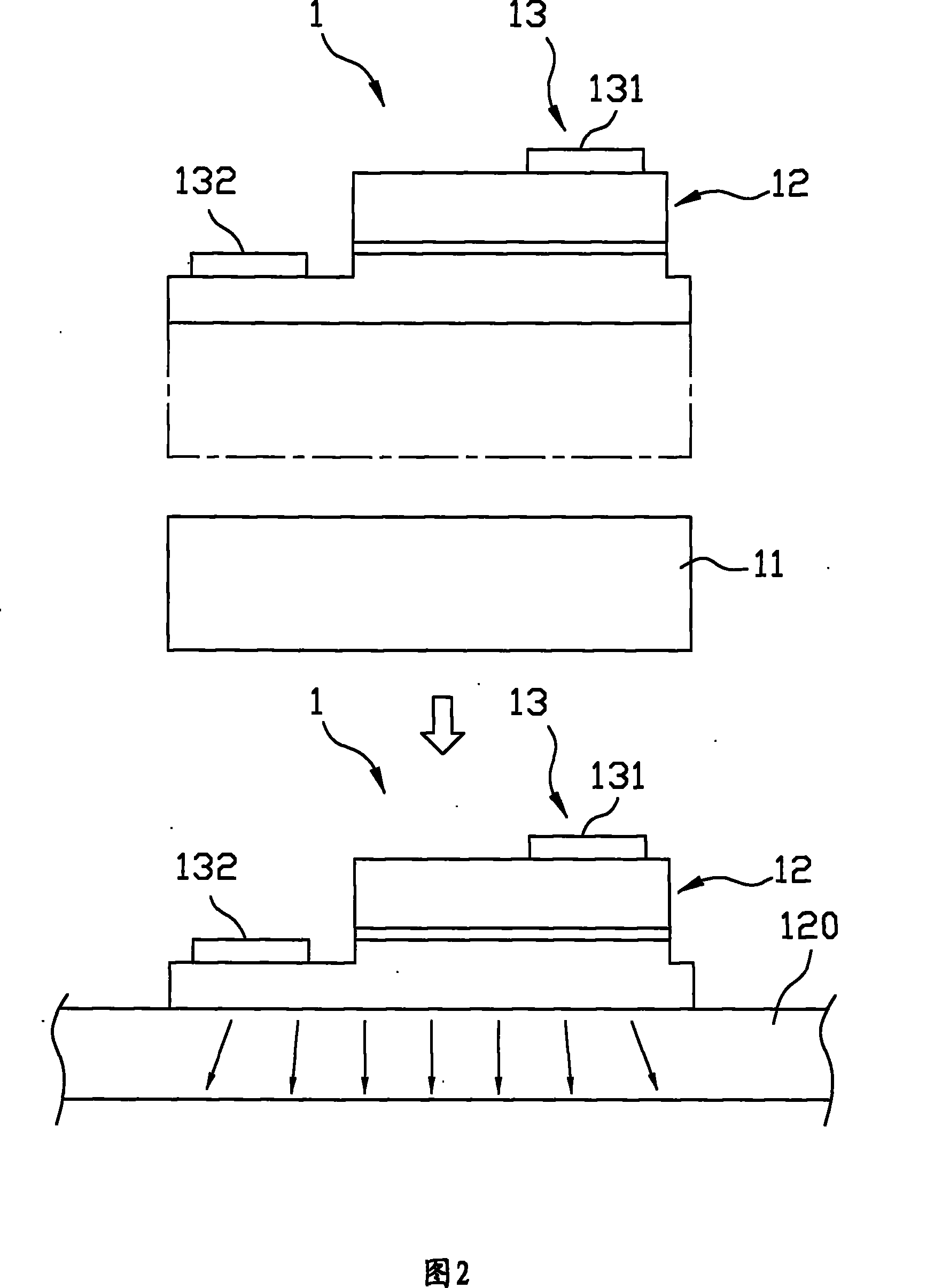
[0008]Refer to Figure 2. Recently, wafer bonding technology (wafer bonding) has also been used to solve the heat dissipation problem of light-emitting diodes. The substrate 11 of the semiconductor material is removed, and the structures such as the operating film 12 and the electrode unit 13 are "bonded" to the semiconductor substrate 120 whose thermal conductivity is higher than that of the original substrate, such as "bonding" on the silicon substrate. In this way, the operating film 12 The heat generated during operation can be quickly conducted away from the operating film 12 itself through the semiconductor substrate 120 to conduct to the outside world and reduce the temperature of the joint surface; In the process of removing the substrate 11 for epitaxy, the active film 12 will undergo a momentary high stress change and cause lattice defects, which will cause the element to produce an irreversible leakage phenomenon

Method used


Image

  • Light emitting diode apparatus having heat conductive substrate
  • Light emitting diode apparatus having heat conductive substrate
  • Light emitting diode apparatus having heat conductive substrate

Examples


Embodiment Construction

[0024] The light-emitting diode device with a heat-conducting base of the present invention will be described in detail below with reference to the drawings and embodiments.

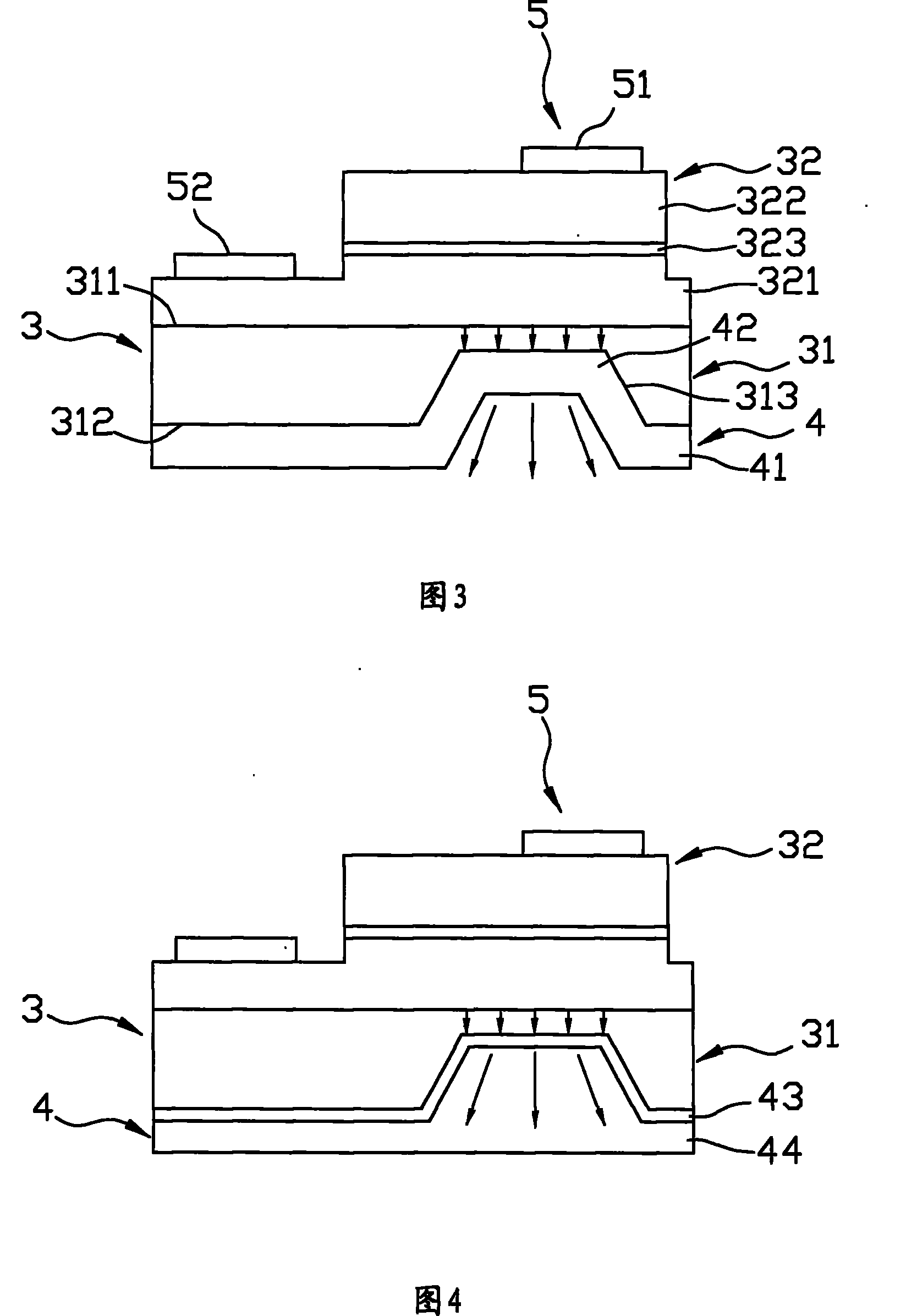
[0025] Referring to FIG. 3 , the first preferred embodiment of the light-emitting diode device with heat-conducting base of the present invention includes: a light-emitting diode chip 3 , a heat-conducting base 4 and a set of electrode units 5 .

[0026] This light emitting diode chip 3 has a base material 31 and a layer of action film 32, which is similar to the existing light emitting diode chip. Made of sapphire, it includes a top surface 311, a bottom surface 312 opposite to the top surface 311, and at least one filling hole 313 formed on the bottom surface 312. In this example, only a single filling hole 313 is shown for illustration .

[0027] This layer of action film 32 is similar to the action film 12 of the current light-emitting diode chip 1, and is usually selected from gallium nitride semic...


PUM


Abstract

A light emitting diode (LED) device with a heat conduction base comprises an LED wafer, a heat conduction base connected with the LED wafer and an electrode unit used for providing electric energy. The LED wafer is provided with a base material with at least a filling hole formed on the bottom surface and an action film which is arranged on the base material and generates light while providing electric energy; the heat conduction base is composed of materials with high heat transfer coefficient, a base connected with the bottom surface of luminescent base material and a bump which extends upward from the base in a convex way and correspondingly fills the filling hole. The heat generated when the LED wafer operates can be directly and rapidly conducted to the outside from the bump and baseof the heat conduction base after being conducted via an extremely short base material route, thus simply and effectively reducing the temperature of the operation joint face and increasing the overall luminosity and working life.

Description

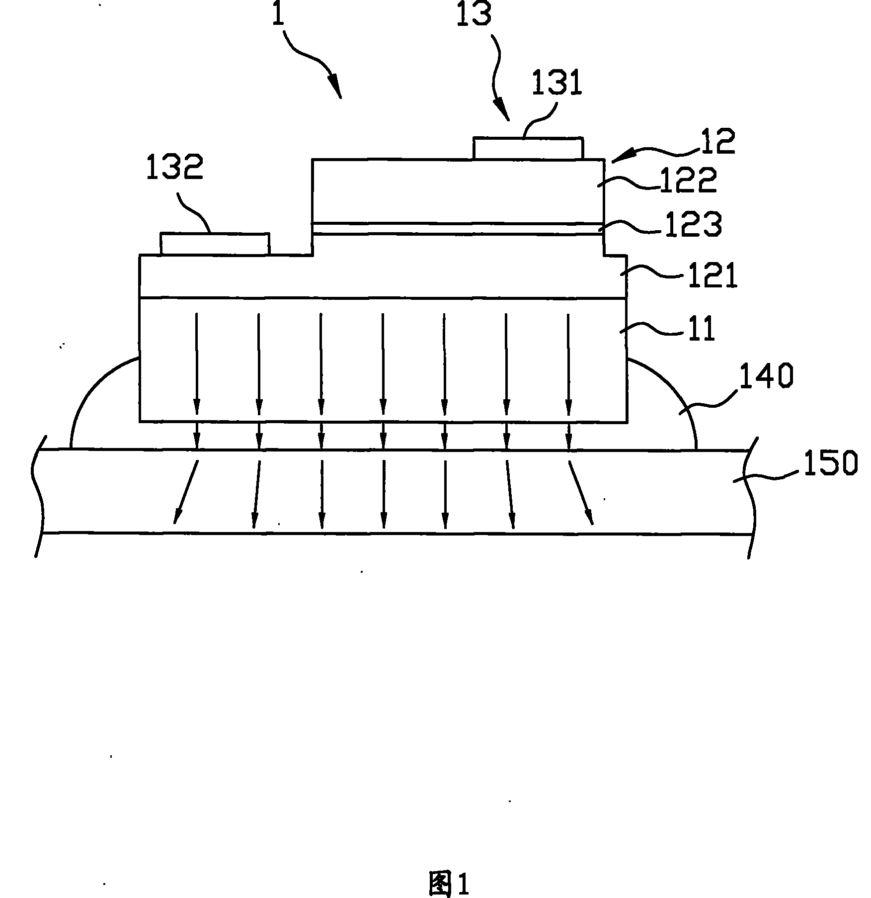
technical field [0001] The invention relates to a light emitting diode device, in particular to a light emitting diode device with a heat conduction base. Background technique [0002] Referring to FIG. 1 , a general LED chip 1 includes a substrate 11 , a layer of action film 12 connected to the substrate 11 and a group of electrode units 13 for providing electric energy. [0003] The substrate 11 is made of a material that is easy for epitaxial growth of gallium nitride-based semiconductor materials, such as sapphire. [0004] This layer of action film 12 is usually selected from gallium nitride-based semiconductor materials, and is epitaxially formed from the substrate upwards, and has first and second cladding layers 121, 122 (n- type cladding layer, p-type cladding layer), and an active layer 123 (active layer) formed between the first and second cladding layers 121, 122, the first cladding layer 121 and the second cladding layer 122 are opposite The active layer 123 f...

Claims


Application Information

Patent Timeline
Patent Type & Authority Patents(China)
IPC IPC(8): H01L33/00H01L23/36
Inventor 陈锡铭朱长信
Owner CHI MEI LIGHTING TECHNOLOGY CORP
Learn More