
Electronic module with integrated programmable thermoelectric cooling assembly and method of fabrication

Inactive Publication Date: 2004-07-27
IBM CORP
View PDF15 Cites 40 Cited by
  • Summary
  • Abstract
  • Description
  • Claims
  • Application Information

AI Technical Summary

Benefits of technology

Thermoelectric devices, used in conjunction with other module cooling technologies, are known to be able to lower junction temperatures below that which can be achieved by the other module cooling technologies alone. Problems arise, however, when thermoelectric devices are taken down in temperature below the ambient, and in particular, below the environment dew point temperature. Traditionally, thermoelectric devices, which are separate from and attached to an electronic module casing (i.e., cap) are exposed to the system environment. When brought down in temperature below the dew point, condensation forms. This condensation significantly reduces the fatigue life due to corrosion of the solder joints forming the thermoelectric junctions. In fact, the mere presence of oxygen accelerates solder fatigue cracking.
Advantageously, disclosed herein is a means for improving thermoelectric device reliability when used in conjunction with cooling of electronic modules. Specifically, a thermoelectric apparatus is integrated within an electronic module itself so that the thermoelectric apparatus is maintained in a controlled, i.e., oxygen and moisture restricted, environment. Furthermore, by integrating a thermoelectric apparatus into the electronic module, power delivery to the thermoelectric devices can be integrated with the module, thus simplifying system level design, i.e., in comparison with delivering power to externally mounted thermoelectric devices.
As a further enhancement, by integrating thermoelectric cooling assemblies within the electronic module, power delivery to the thermoelectric elements can be simplified by eliminating discrete wiring outside of the module. Wire bond or electrical spring contacts can be employed within the module to couple the thermoelectric stages to appropriate power planes, e.g., disposed within the substrate of the module.

Problems solved by technology

Conventional configurations and positionings of thermoelectric assemblies are nonetheless seen herein to be unnecessarily limiting in terms of the thermal energy which may be transferred and the long term reliability attained.
Thus, while the use of thermoelectric devices is seen to provide a means for the solid state cooling of adjacent electrical devices, their efficiency and reliability has been less than optimal.
However, conventional refrigeration systems may be difficult to control for variations in heat load, and may not be responsive enough during transient operating conditions.
Problems arise, however, when thermoelectric devices are taken down in temperature below the ambient, and in particular, below the environment dew point temperature.
This condensation significantly reduces the fatigue life due to corrosion of the solder joints forming the thermoelectric junctions.
In fact, the mere presence of oxygen accelerates solder fatigue cracking.

Method used


Image

  • Electronic module with integrated programmable thermoelectric cooling assembly and method of fabrication
  • Electronic module with integrated programmable thermoelectric cooling assembly and method of fabrication
  • Electronic module with integrated programmable thermoelectric cooling assembly and method of fabrication

Examples


Embodiment Construction

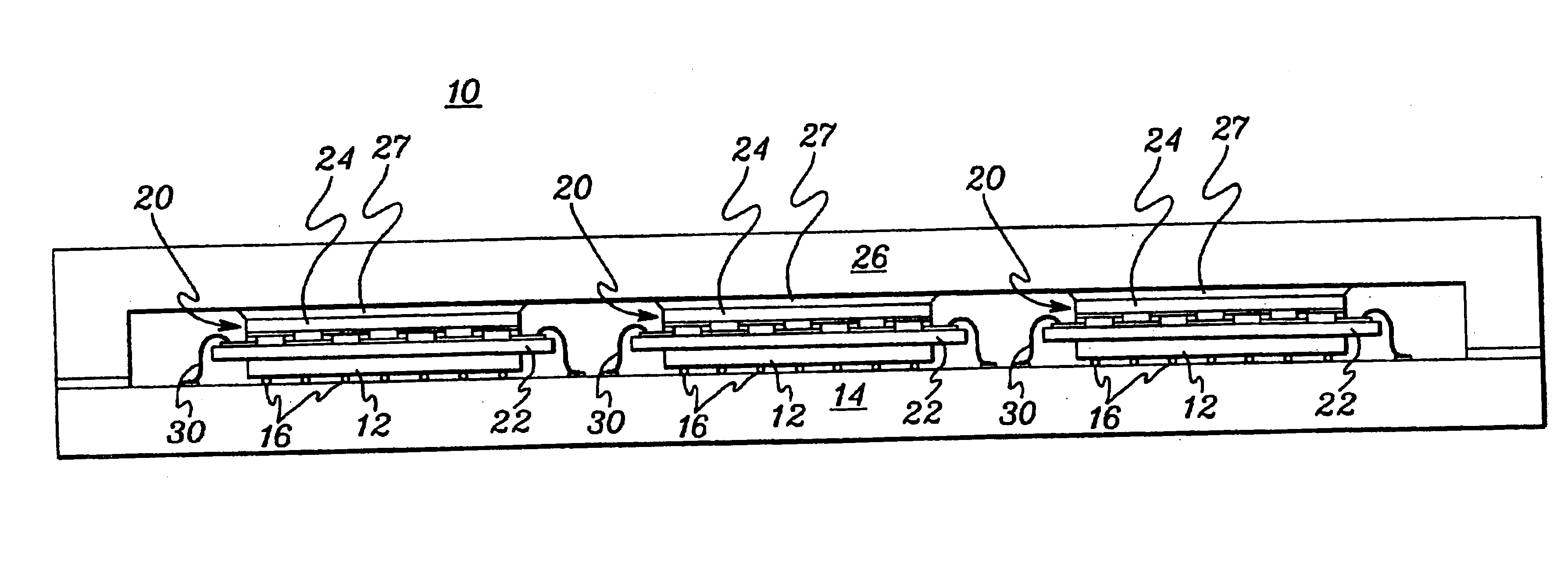
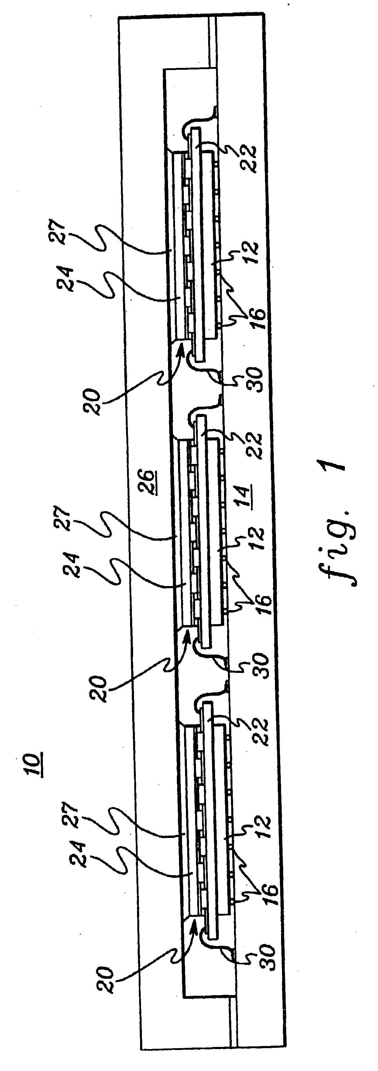
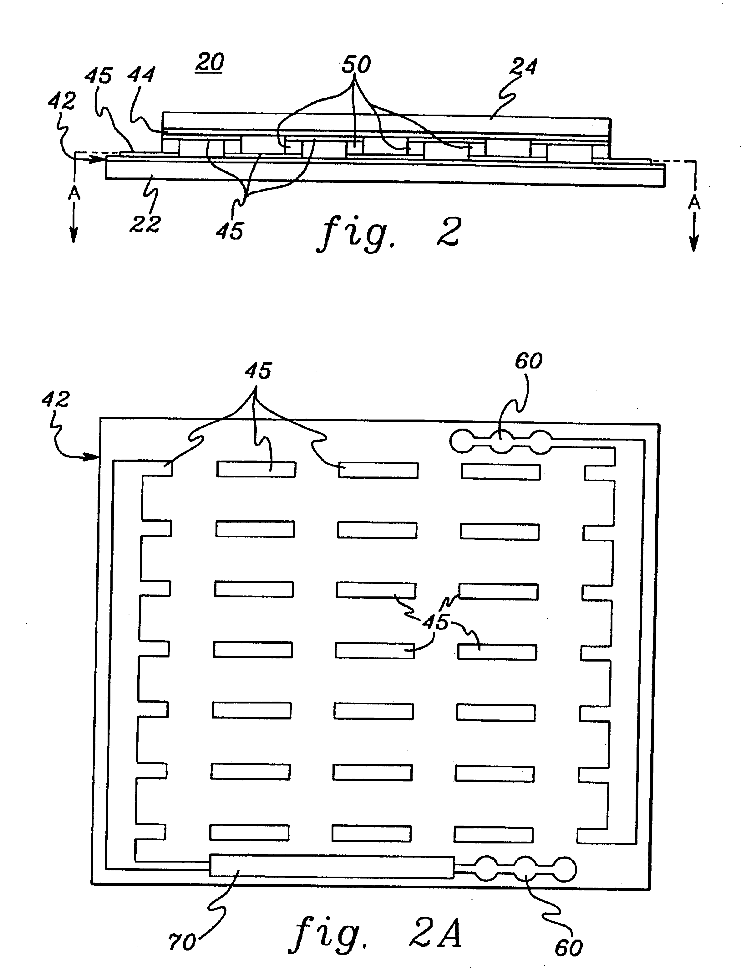
Generally stated, provided herein is an electronic module with an integrated thermoelectric cooling assembly for removing heat from an electronic device thereof, such as an integrated circuit chip. The thermoelectric cooling assembly and electronic device are sealed together within the module, for example, between a substrate and a thermally conductive cap. In one embodiment, a module comprises a multi-chip module (MCM) wherein each electronic device within the module has coupled thereto a programmable thermoelectric cooling assembly in accordance with the present invention. Each programmable thermoelectric cooling assembly has a same number and geometry of thermoelectric elements, but can be tailored (i.e., programmed) through a power control circuit integrated into each thermoelectric assembly. For example, the power control circuit may comprise a series of voltage boost circuits which (using laser delete techniques) may be added or removed to adjust a voltage level to each thermo...


PUM


Abstract

An electronic module and method of fabrication are provided employing an integrated thermal dissipation assembly. The thermal dissipation assembly includes a thermoelectric assembly configured to couple to an electronic device within the module for removing heat generated thereby, and a programmable power control circuit integrated with the thermoelectric assembly. The programmable power control circuit allows cooling capacity of the thermoelectric assembly to be tailored to anticipated heat dissipation of the electronic device by adjusting, for a given power source, voltage level to the thermoelectric elements of the thermoelectric assembly. Power to the thermoelectric assembly can be provided through conductive power planes disposed within a supporting substrate. The power control circuit includes one or more voltage boost circuits connected in series between the given power source and the thermoelectric elements of the associated thermoelectric assembly.

Description

TECHNICAL FIELDThe present invention is directed to cooling assemblies and other apparatus used for removing heat from electronic devices. More particularly, the present invention is directed to an electronic module with integrated thermoelectric cooling elements. Even more particularly, this invention is directed to an enhanced thermoelectric apparatus having an integrated power control circuit which provides a programmable voltage level from a given power source, to allow customization of the cooling capacity of the thermoelectric assembly when the thermoelectric assembly is interposed within an electronic module in thermal contact with a heat generating component thereof, such as an integrated circuit chip.BACKGROUND OF THE INVENTIONAs is well known, as the circuit density of electronic chip devices increases, there is a correspondingly increasing demand for the removal of heat generated by these devices. The increased heat demand arises both because the circuit devices are packe...

Claims


Application Information

Patent Timeline
IPC IPC(8): H01L23/38H01L23/34
CPCH01L23/34H01L23/38H01L2224/16225H01L2224/48091H01L2224/73253H01L2924/16152H01L2924/00014H01L2224/0401
Inventor CHU, RICHARD C.ELLSWORTH, JR., MICHAEL J.SIMONS, ROBERT E.
Owner IBM CORP
Learn More