Malodorous gas processing system and processing method thereof

A technology for treating system and malodorous gas, applied in the direction of separation methods, chemical instruments and methods, chemical/physical/physicochemical processes using energy, etc., can solve the problems of high recombination rate, slow transfer speed, low reaction conversion rate, etc. Achieve high degree of mineralization and better deodorization effect

Inactive Publication Date: 2009-08-05
WUHAN UNIV OF SCI & TECH
View PDF0 Cites 5 Cited by
  • Summary
  • Abstract
  • Description
  • Claims
  • Application Information

AI Technical Summary

Problems solved by technology

However, the transfer speed of photogenerated electron and hole pairs is slow and the recombination rate is high, resulting in low photocatalytic quantum efficiency and low reaction conversion rate.

Method used


Image

  • Malodorous gas processing system and processing method thereof

Examples


Embodiment 1

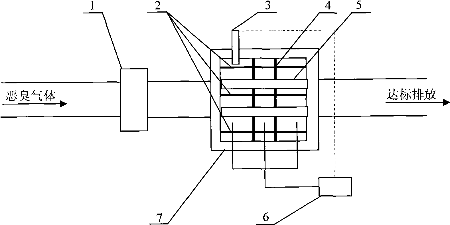
[0016] A treatment system and treatment method for malodorous gas, the adopted technical scheme is divided into treatment system and treatment method, the treatment system is as follows figure 1 As shown: the ultraviolet lamp tube 5 and the rectifying photocatalyst plate 4 are installed in the processing box 7, the ultraviolet lamp tube 5 passes through the rectifying photocatalyst plate 4 vertically, and the inner wall of the processing box 7 and the rectifying photocatalyst plate 4 are evenly coated with nano-scale TiO 2 , activated carbon fiber 2 is placed in the treatment box 7; the humidity sensor 3 is placed in the treatment box 7, the humidifier 6 communicates with the treatment box 7 through a pipeline; the blower fan 1 communicates with the air inlet of the treatment box 7 through an air supply pipe, and the treatment box The air outlet of 7 communicates with atmosphere.

[0017] Wherein, the activated carbon fiber 2 is placed 0.07-0.1 m away from the ultraviolet lamp...

Embodiment 2

[0020] A treatment system and treatment method for malodorous gas, the technical scheme adopted is divided into treatment system and treatment method, the treatment system is as follows figure 1 As shown, except that the activated carbon fiber 2 is placed 0.07-0.1 m away from the ultraviolet lamp 5 and placed in strips parallel to the ultraviolet lamp 5, the others are the same as in the embodiment 1.

[0021] The treatment method of this treatment system is: the relative humidity in the treatment box 7 in the setting treatment system is 70%~90%, the flow velocity of malodorous gas in the treatment box 7 is 0.5~0.8m / s, the ultraviolet light tube 5 The intensity of ultraviolet radiation is 80~100W / m 2 ; The specific surface area of ​​activated carbon fiber 2 is 1300~1600m 2 / g.

[0022] In Embodiments 1 and 2, the blower 1 transports and homogenizes the malodorous gas, controls the inflow of the malodorous gas, and keeps the flow velocity of the malodorous gas within an appro...


PUM

PropertyMeasurementUnit
specific surface areaaaaaaaaaaa

Abstract

The invention in particular relates to a system and a method for treating foul gas. The treating system comprises that: an ultraviolet strip lamp (5) and a rectification photocatalytic plate (4) are arranged inside a treating tank (7); the ultraviolet strip lamp (5) vertically runs through the rectification photocatalytic plate (4); the inner wall of the treating tank (7) and the rectification photocatalytic plate (4) are evenly coated with nanometer level TiO2; the inside of the treating tank (7) is provided with active carbon fibre (2); a humidifier (6) is communicated with the treating tank (7) through a pipeline; and a draught fan (1) is communicated with a wind inlet of the treating tank (7) through a wind feeding pipe. The relative humidity of the treating tank (7) of the treating system is between 50 and 90 percent; the flow speed of the foul gas in the treating tank (7) is between 0.2 and 0.8 m / s; the ultraviolet irradiation strength of the ultraviolet strip lamp (5) is between 50 and 100 W / m; the specific surface area of the active carbon fibre (2) is between 900 and 1,600 m / g; and the active carbon fibre (2) is embedded or is not embedded into nanometer level TiO2 powder. The system and the method have the characteristics of simple process, reliable operation, high efficiency and no secondary pollution.

Description

technical field [0001] The invention belongs to the technical field of malodorous gas treatment. In particular, it relates to a malodorous gas treatment system and a treatment method thereof. Background technique [0002] "National Standard of the People's Republic of China - Odor Pollution Emission Standard" (GB14554-93) defines stench as: all gaseous substances that stimulate the olfactory organs, cause people's unpleasantness and damage the living environment. In order to protect and improve the sanitation quality of various processing sites and the surrounding environment, and reduce secondary pollution to the air, it is very necessary to effectively control the stench. [0003] At present, the domestic and international methods of controlling stench mainly include chemical deodorization method, physical and chemical deodorization method and biological deodorization method. Among them, chemical deodorization methods mainly include ozone oxidation method, photocatalytic...

Claims


Application Information

Patent Timeline
Patent Type & Authority Applications(China)
IPC IPC(8): B01D53/86B01D53/04A61L9/014A61L9/20B01J19/12
Inventor 任大军康志坚雷力田从辉
Owner WUHAN UNIV OF SCI & TECH
Why Eureka
Try Eureka