Hydrogen generating apparatus and fuel cell system

A generation device and combustion gas technology, applied in fuel cells, hydrogen/synthesis gas production, hydrogen, etc., can solve problems such as insufficient removal of carbon monoxide

Active Publication Date: 2009-08-05
PANASONIC CORP
View PDF1 Cites 6 Cited by
  • Summary
  • Abstract
  • Description
  • Claims
  • Application Information

AI Technical Summary

Problems solved by technology

[0009] Then, there arises a problem as follows: When the temperature distribution of the carbon monoxide reducer 10 in the above-mentioned form is large in the direction perpendicular to the flow direction of the reformed gas, then although it is preferable to The outlet temperature in the converter is about 200°C as described above, but there may be a part lower than 200°C in the thickness direction of the outlet of the carbon monoxide reducer 10, so that there will be a part that is lower than 200°C. A catalyst that does not contribute to the reaction of carbon monoxide may not be able to sufficiently remove carbon monoxide by the carbon monoxide remover 10

Method used


Image

  • Hydrogen generating apparatus and fuel cell system
  • Hydrogen generating apparatus and fuel cell system
  • Hydrogen generating apparatus and fuel cell system

Examples


Embodiment approach 1

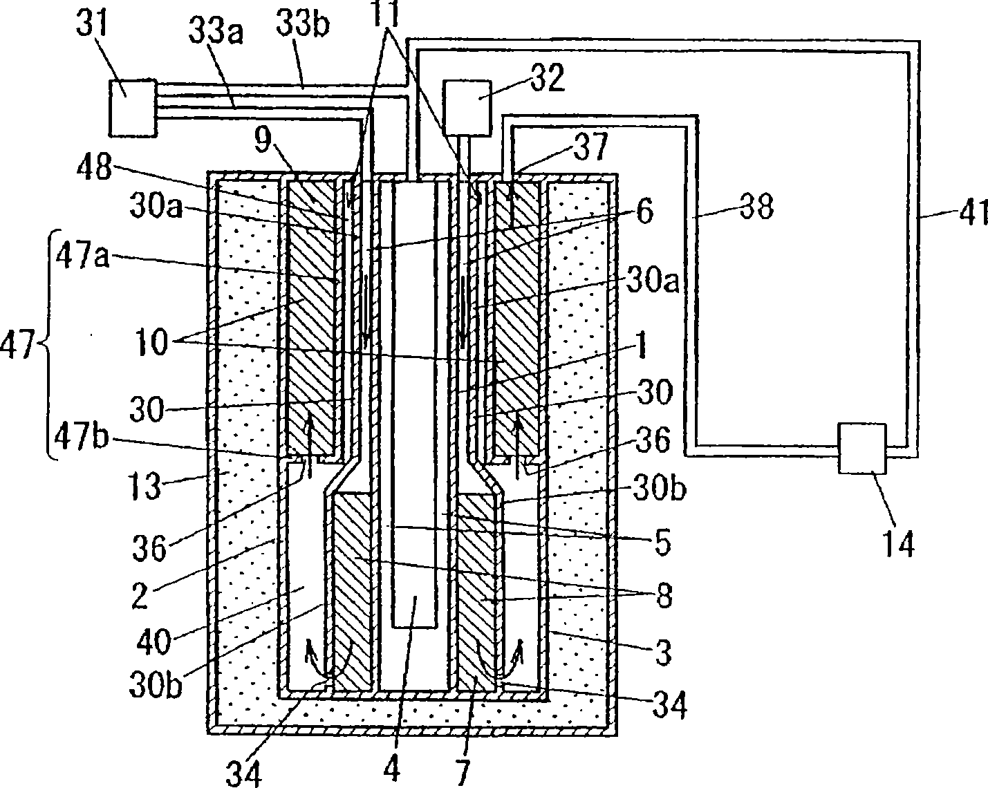
[0081] figure 1 It is a cross-sectional view schematically showing the configuration of the hydrogen generator and the fuel cell system according to Embodiment 1 of the present invention. Such as figure 1 As shown, in this embodiment, the cylindrical body 3 serving as the frame of the device is formed by arranging the cylindrical inner cylinder (partition wall) 1 and the outer cylinder (partition wall) 2 in a concentric two-layer cylindrical shape with the axial direction as the longitudinal direction. And formed. The upper and lower ends of the cylindrical body 3 are closed. A burner 4 constituted by a burner is provided at the center of the inner circumference of the inner cylinder 1 , and a combustion gas passage 5 is formed between the burner 4 and the inner cylinder 1 along the inner circumference of the inner cylinder 1 . The combustion gas passage 5 communicates with the outside (atmosphere) through an outlet (not shown).

[0082]Between the inner cylinder 1 and t...

Embodiment approach 2

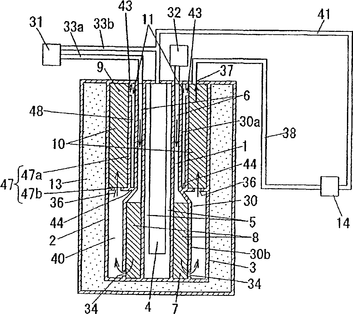
[0101] figure 2 It is a cross-sectional view schematically showing the configuration of a hydrogen generator and a fuel cell system according to Embodiment 2 of the present invention. Such as figure 2 As shown, in this embodiment, the lower end of the heat transfer buffer space 48 is blocked with the cover plate 44 to prevent it from communicating with the reformed gas circulation path 40, and at the same time, the isolation of the inner periphery of the carbon monoxide reducer 10 is defined. The communication port 43 is provided in the upper part of the vertical wall 47a of the wall 47, and is provided so that the heat transfer buffer space 48 may communicate with the carbon monoxide reducer 10. As for other components and figure 1 means the same.

[0102] In this configuration, since the heat transfer buffer space 48 and the carbon monoxide reducer 10 are communicated through the communication port 43 , low CO concentration reformed gas from which carbon monoxide has b...

Embodiment approach 3

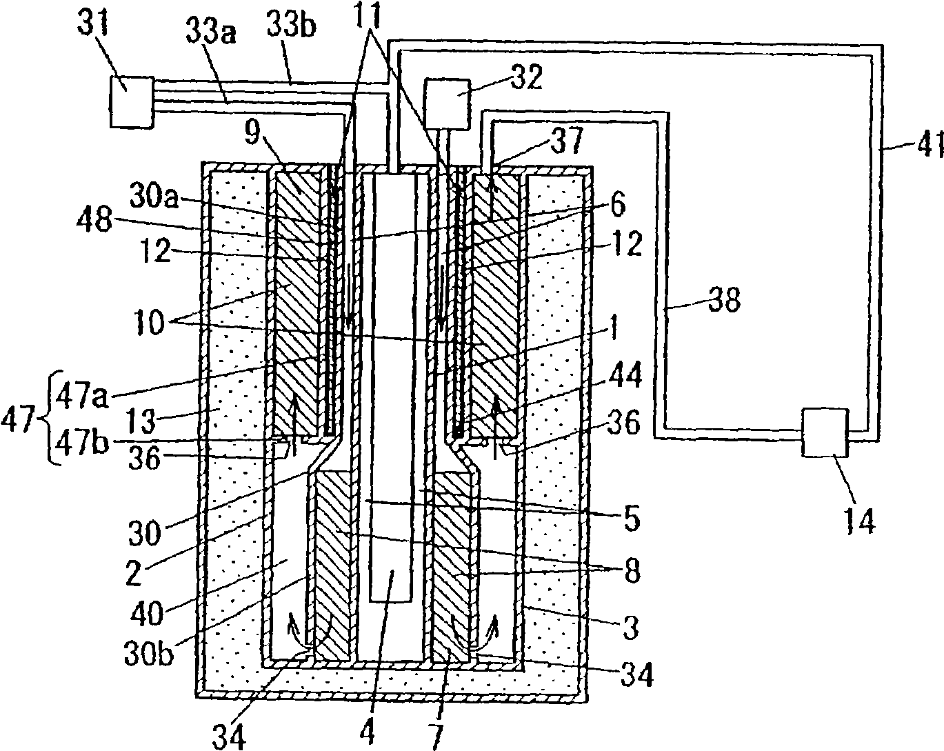
[0104] image 3 It is a cross-sectional view schematically showing the configuration of a hydrogen generator and a fuel cell system according to Embodiment 3 of the present invention. Such as image 3 As shown, in this embodiment, the lower end of the heat transfer buffer space 48 is blocked with the cover plate 44 so as not to communicate with the reformed gas circulation path 40, and at the same time, the upper end of the heat transfer buffer space 48 is defined The upper wall of the body 3 is opened so as to communicate with the outside of the cylinder body 3 . Therefore, the heat transfer buffer space 48 is isolated from the inside of the barrel 3 . In addition, the heat transfer buffer space 48 is filled with the heat transfer member 12 . The thermally conductive member 12 is made of, for example, an appropriately selected metal having good thermal conductivity. As for the other components are the same as figure 1 means the same.

[0105] In the present embodiment,...


PUM


Abstract

A hydrogen generating apparatus comprising combustion gas duct (5) for flow of combustion gas from a combustor; preheater evaporator (6) adapted to be fed with raw gas and water and to evaporate the water and heat the raw gas by heat transferred via partition walls from carbon monoxide cutdown unit (10) and the combustion gas duct; reformer (7) adapted to produce a reformate gas from the raw gas and steam fed from the preheater evaporator with the use of reforming catalyst (8) and heat transferred via partition wall from the combustion gas duct; carbon monoxide cutdown unit (10) adapted to remove any carbon monoxide contained in the reformate gas fed from the reformer with the use of carbon monoxide removing catalyst (9); and tubular body (3) having its both ends closed wherein, dividing the interior space thereof by partition walls (1),(2)(30),(47), the combustion gas duct, preheater evaporator, reformer and carbon monoxide cutdown unit are provided thereinside. Between the preheater evaporator and the carbon monoxide cutdown unit, there is provided heat transfer buffer part (11) composed of partition wall (30) defining the preheater evaporator and partition wall (47) defining the carbon monoxide cutdown unit, disposed opposite to each other with a spacing therebetween.

Description

technical field [0001] The present invention relates to a fuel cell system comprising: a hydrogen generator for producing hydrogen-rich reformed gas using hydrocarbon-based fuel such as city gas or LPG as a raw material gas; and power generation using hydrogen produced by the hydrogen generator fuel cell. Background technique [0002] The main components of the fuel cell system are a hydrogen generator that produces a hydrogen-rich reformed gas, and a fuel cell that generates electricity using the hydrogen produced by the hydrogen generator. [0003] In addition, the hydrogen generation device is equipped with a reformer that uses hydrocarbon-based fuel such as city gas or LPG as a raw material gas, and generates hydrogen, methane, and carbon monoxide (10 %), carbon dioxide, and water vapor reformed gas; the carbon monoxide removal unit removes carbon monoxide, which has a poisoning effect on the fuel cell, from the reformed gas. Here, when a solid polymer fuel cell is use...

Claims


Application Information

Patent Timeline
Patent Type & Authority Applications(China)
IPC IPC(8): C01B3/38H01M8/06
CPCC01B2203/0822B01J2208/00504C01B3/384Y02E60/50B01J8/0469H01M8/0631C01B2203/0827C01B2203/066B01J8/0496C01B2203/0811B01J2208/00495C01B2203/047C01B2203/0233B01J8/0465Y02P20/10
Inventor 向井裕二前西晃鹈饲邦弘中村透
Owner PANASONIC CORP
Why Eureka
Try Eureka