
Milling cutter for high speed machining of non-metallic material

A technology of non-metallic materials and milling cutters, which is applied in the direction of milling cutters, metal processing equipment, manufacturing tools, etc., can solve the problem of not being able to meet the requirements of high-speed and high-precision processing of non-metallic materials, the influence of the surface quality and dimensional accuracy of the processing object, and the cutting edge Parts are easy to be stuffed and other problems, so as to achieve the effect of light cutter body, smooth chip removal and smooth chip discharge

Inactive Publication Date: 2009-08-12
HUNAN UNIV
View PDF0 Cites 9 Cited by
  • Summary
  • Abstract
  • Description
  • Claims
  • Application Information

AI Technical Summary

Problems solved by technology

At present, the overall milling cutter produced by domestic and foreign tool manufacturers has a small helix angle, a small rake angle, and a short blade length. Due to the influence of the structure, this type of tool has a small single-tooth chip removal space and a narrow rake face. The weight is heavy. When milling non-metallic materials such as resin, foam, sludge, plastic, etc., especially during high-speed machining, it is difficult to discharge soft chips and the cutting edge is easy to be filled, which affects the surface quality and dimensional accuracy of the processed object. , and the heavier tool has potential harm to the electric spindle when it rotates at high speed, and cannot meet the high-speed and high-precision machining requirements of non-metallic materials

Method used


Image

  • Milling cutter for high speed machining of non-metallic material
  • Milling cutter for high speed machining of non-metallic material
  • Milling cutter for high speed machining of non-metallic material

Examples


Embodiment Construction

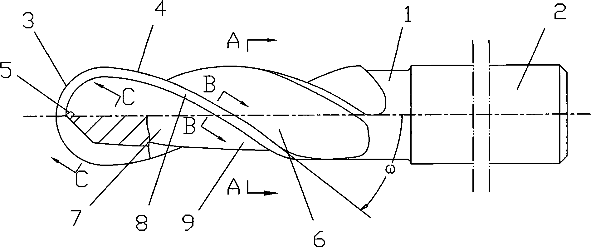
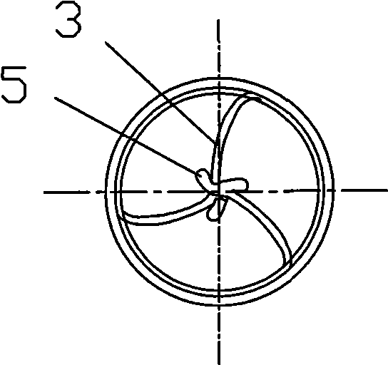
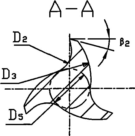
[0013] See figure 1 , figure 2 , image 3 , Figure 4 , Figure 5 with Figure 6 , The cutter body part 1 is composed of three (or two) main cutting edges 3, secondary cutting edges 4, rake faces 6 and flank faces 7 at the end of the ball nose cutter body, and the adjacent main cutting edges 3 are arranged between There is a transition groove edge 5, the helix angle ω of the secondary cutting edge 4 is 60°, and the rake angle a of the main cutting edge 3 1 And back angle β 1 Both are 15°, the rake angle of the secondary cutting edge 4 a 2 12°, clearance angle β 2 The radius D4 of the arc groove of the main cutting edge 3 is 1.5mm, and the radial cross-sectional shape of the spiral groove forming the rake face 6 is a circular arc with a radius D2 of 3.5mm. The flank 7 is composed of A main flank 8 with a width D1 of 1.5mm and a secondary flank 9 with a radius D3 of 7.5mm in a radial section. The blade length of the body part 1 is 60mm, and the knife diameter D5 is 20mm.

[0014] ...


PUM


Abstract

The invention discloses a milling cutter used for processing non-metal materials at high speed. Transitional groove edges (5) are arranged between adjacent main cutting edges (3); the helical angle omega of an minor cutting edge (4) is 50 to 60 degrees; the front angle alpha1 and the rear angle of beta1 of the main cutting edges (3) are 15 degrees; the front angle alpha2 of the minor cutting edge (4) is 12 degrees and the rear angle is 15 degrees; circular arc groove radii D4 of the main cutting blades (3) are 1.5mm to 3.5mm; the radial section of a helical groove of a rake face (6) is a circular arc with radius D2 of 3.5mm to 6mm; a flank (7) consists of a main flank (8) with width D1 of 1.5mm and a minor flank (9) with radial section being an circular arc with 7.5mm to 15mm of radius D3; the diameter D of the cutter is 20 to 50mm. The invention with the advantages of high cutting efficiency, small cutting resistance, smooth chip removal, light body and good intensity is applicable to the high-speed coarse and fine milling of foam, resin, plastic, organic glass and other non-metal chemical materials.

Description

Technical field [0001] The invention relates to a milling cutter, in particular to a milling cutter used for high-speed cutting of non-metallic materials, especially a high-speed integral end mill used for milling resin, foam, sludge, plastic and other materials. Background technique [0002] When cutting non-metallic materials, such as resin, foam, sludge and plastics, their material is soft, chip removal is difficult, and the surface roughness of the machine is not high. The two main difficulties faced by machining personnel have always been. When cutting such materials, we noticed that chips often adhere to the cutting edge part of the tool easily, filling the chip removal space of the cutting edge. Poor chip removal greatly affects the processing quality (including dimensional accuracy, processed surface quality, etc.), especially in high-speed processing, the linear speed and feed speed of the tool are both high, and its impact is even greater obvious. At present, the integr...

Claims


Application Information

Patent Timeline
Patent Type & Authority Applications(China)
IPC IPC(8): B23C5/02
Inventor 杨旭静朱克忆王伏林
Owner HUNAN UNIV
Learn More