Temperature control method of fluidized bed reactor

A fluidized bed reactor, temperature control method technology, applied in the direction of temperature control, chemical instruments and methods, non-electrodynamic variable control, etc. Effect

Active Publication Date: 2009-08-19
ASAHI KASEI KK
View PDF2 Cites 10 Cited by
  • Summary
  • Abstract
  • Description
  • Claims
  • Application Information

AI Technical Summary

Problems solved by technology

As a result, there is a tendency that the complete oxidation product increases and the selectivity of the target product decreases.

Method used


Image

  • Temperature control method of fluidized bed reactor

Examples


Embodiment 1

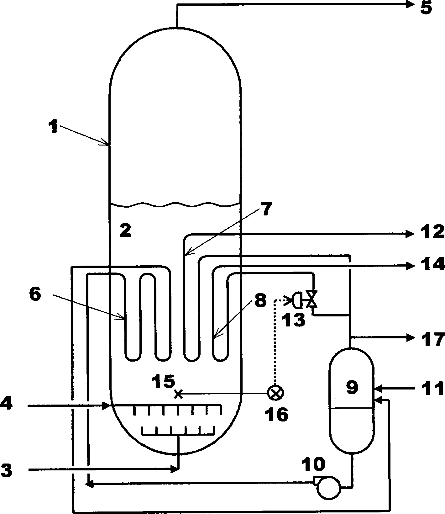
[0107] Xiang Ru figure 1 A fluidized bed reactor (1) with a diameter of 6.82 m in the form shown is filled with 80 tons of composite oxide catalysts, wherein the catalysts are composed of molybdenum, vanadium, antimony and niobium, with an average particle size of 50 μm and containing 12% Fine powder with a particle size of 44 μm or less. Supply air 45000Nm from the oxygen supply pipe (3) 3 / Hr, supply mixed propane 3000Nm from raw material supply pipe (4) 3 / Hr and ammonia 2700Nm 3 / Hr gas, mainly for the manufacture of acrylonitrile.

[0108] The fluidized bed (2) is equipped with conventional heat removal pipes (6) 30 series (the total length of the straight pipe part is 1250m), and the pipes use steel pipes with an outer diameter of 114.3mm specified in JIS G-3458 and corresponding to those specified in JIS B-2311. It is made of butt welded 180° large radius elbow. Supply 800 tons / Hr of water at 235°C to these conventional heat removal pipes (6) from the gas-liquid s...

Embodiment 2

[0114] In Example 1, without changing the set temperature and specified value, set the regulating valve so that the heat removal capacity of the heat removal pipe (8) can be adjusted from 100% of the adjustable range FS to 100% with an average change rate of 0.2FS / min. 0% change, or, change from 0% to 100%, automatic control operation is performed. At this time, the fluctuation range of the reactor temperature is 444-446°C, and it can be automatically controlled within the range of ±1°C relative to the set temperature.

[0115] In this embodiment, a K-type thermocouple is installed in the center of the fluidized bed as a temperature detector (15), and a temperature regulator (16) is used to convert the thermal electromotive force into a temperature signal for detection. In the temperature regulator (16), based on the difference between the detected temperature of the reactor and the set temperature, the DCS device CS3000 manufactured by Yokogawa Electronics Co., Ltd. is used t...

Embodiment 3

[0117] Perform PID calculation through DCS device, set control variables (P: proportional band, I: integral time, D: differential time), so as to make the heat removal capacity of heat removal pipe (8) from The ammoxidation reaction of propane was carried out in the same manner as in Example 1, except that the automatic control operation was performed by changing from 100% of the adjustable range FS to 0%, or from 0% to 100%. At this time, the fluctuation range of the reactor temperature is 444.5-445.5°C, which can be automatically controlled within the range of ±0.5°C relative to the set temperature.


PUM


Abstract

The invention provides a temperature control method, which can more precisely control the temperature in a fluidized bed reactor when the fluidized bed reactor is used for implementing gas-phase exothermal reaction. The method for controlling the temperature when the fluidized bed reactor which is provided with a general heat extraction pipe, a heat extraction adjusting pipe and a temperature detector is used for implementing the gas-phase exothermal reaction comprises the following steps: (i) performing heat extraction through the general heat extraction pipe, and simultaneously detecting the temperature of the fluidized bed reactor through the temperature detector; and (ii) converting the heat extraction capacity of the heat extraction adjusting pipe from less than 10 percent of the adjustable range FS to more than 90 percent or from more than 90 percent to less than 10 percent at the average change rate of more than 0.1 FS per minute when the detected temperature deviates from the set temperature so as to adjust the temperature of the fluidized bed reactor to the set temperature.

Description

technical field [0001] The present invention relates to a temperature control method of a fluidized bed reactor, and more specifically, to a temperature control method capable of more precisely controlling the temperature in the reactor when a fluidized bed reactor is used to perform a gas-phase exothermic reaction. Background technique [0002] In the industrial production of monomers useful for the production of various synthetic resins and synthetic fibers by gas-phase exothermic reactions, fluidized bed reactors are widely used. Typical examples of gas-phase exothermic reactions carried out industrially include continuous oxidation reactions such as partial oxidation reactions and ammoxidation reactions in the presence of ammonia gas. In the continuous oxidation reaction, since the oxidation stability of the partial oxidation product which is the target product is usually not so high, the continuous reaction of the target product proceeds as the reaction proceeds, that i...

Claims


Application Information

Patent Timeline
Patent Type & Authority Applications(China)
IPC IPC(8): B01J8/24G05D23/00
Inventor 杉山直树福薗敏彦
Owner ASAHI KASEI KK
Why Eureka
Try Eureka