Continuous mobile waterpower drive device of nuclear reactor control rod

A nuclear reactor and hydraulic drive technology, applied in the control of nuclear reactions, reactors, nuclear engineering, etc., can solve the problem that the control rods are not continuous, and achieve the effects of easy operation and programmed control, good safety and stability, and simple structure

Inactive Publication Date: 2009-08-19
HARBIN ENG UNIV
View PDF0 Cites 10 Cited by
  • Summary
  • Abstract
  • Description
  • Claims
  • Application Information

AI Technical Summary

Problems solved by technology

Its disadvantage is that the movement of the control rod is stepped rather than continuous; it has high requirements for flow control

Method used


Image

  • Continuous mobile waterpower drive device of nuclear reactor control rod
  • Continuous mobile waterpower drive device of nuclear reactor control rod

Examples


Embodiment Construction

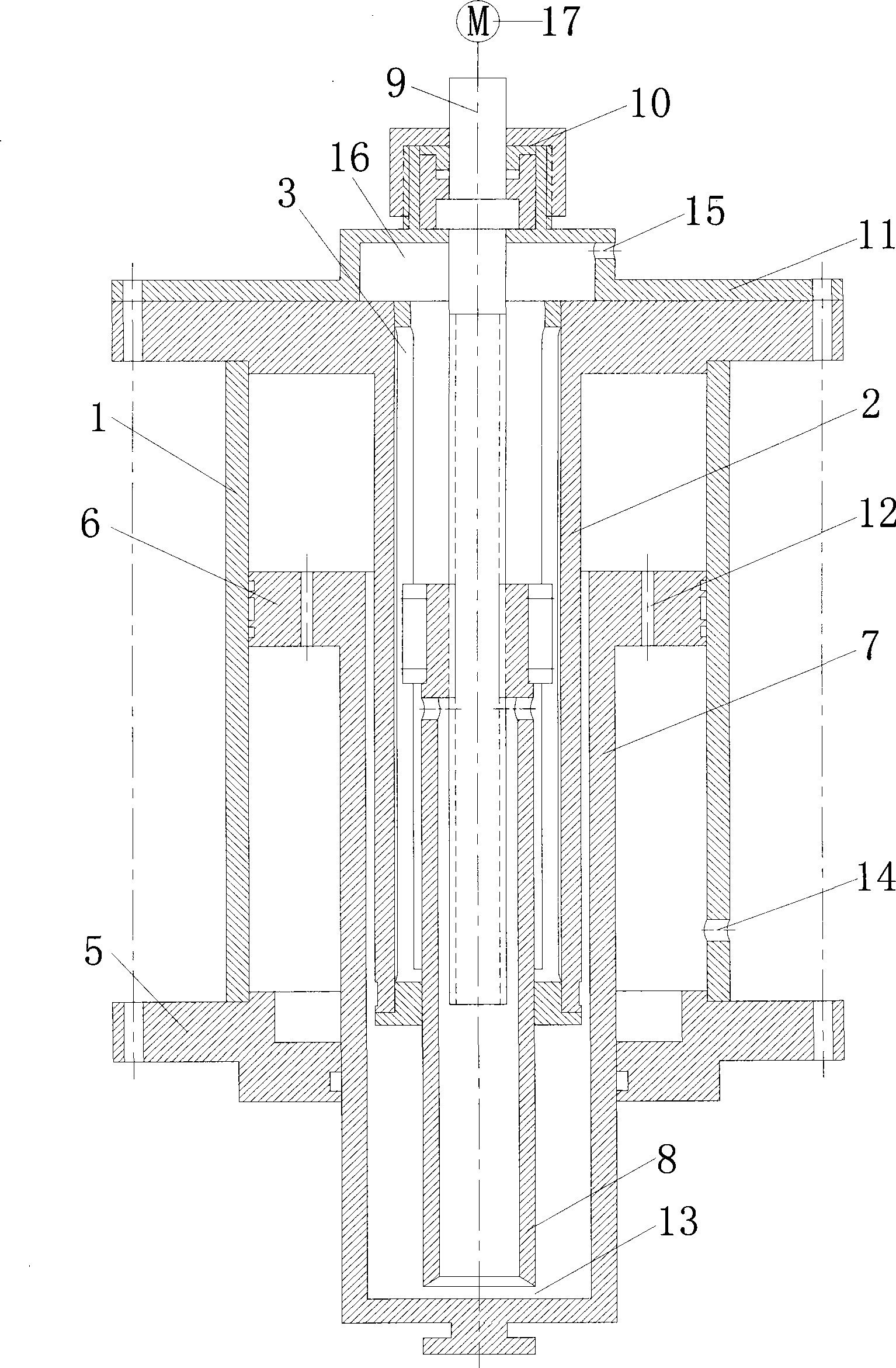
[0016] The present invention is described in more detail below in conjunction with accompanying drawing example:

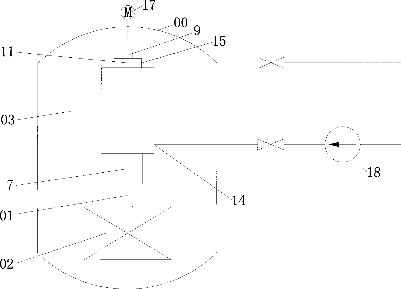
[0017] combine figure 1 , the specific composition of the hydraulic driving device for the control rod of the continuous mobile nuclear reactor includes a driving cylinder 1, an inner sleeve 2, a chute sleeve 3, a lower end cover 5, a piston 6, a hollow piston rod 7, a servo tube 8, a screw 9 and a stopper. Channel assembly 10, buffer chamber cover 11 and its power source (motor 17 and water pump 18 (see figure 2 )); wherein, the integrated piston 6 and hollow piston rod 7 are inserted coaxially with the drive cylinder 1; the inner sleeve 2 inserted in the hollow piston rod 7 is a flange with an end The cylinder body and part of the outer wall are processed into a plane, so that the arc surface on the outer wall can be slidably matched with the hollow piston rod 7, and the plane on the outer wall and the inner wall of the hollow piston rod 7 can form a working m...


PUM


Abstract

The invention provides a continuously moving-type control rod hydraulic drive device of a nuclear reactor, which comprises a drive cylinder barrel, an internal sleeve, a runner sleeve, a lower end cover, a piston, a hollow piston rod, a servo tube, a leading screw, a shift-stopping assembly and a power source (a motor and a water pump). The control rod hydraulic drive device takes a refrigerant (water) in a pressure container of the nuclear reactor as a working substance, and the refrigerant (water) flows along a flowing channel formed internally therein after being pressurized by a water pump; the motor and the auxiliary moving servo tube of screw transmission are used for changing the width of a changeable choke formed between the end surface of the servo tube and the inner bottom surface of the hollow piston rod so as to change the pressure at two sides of the piston and drag a control rod fixedly connected with the outer end of the hollow piston rod to move. The control rod hydraulic drive device has the advantages that since no electron device required for solenoid drive exists, the requirement on working environment is not high; the continuous movement of the control rod can be realized; the drive device has simple structure and convenient processing and is easy for operation and programmed control; the limitation change range of the pressure and flow of working water is relatively wide, and the drive device has good safety and stability.

Description

(1) Technical field [0001] The invention relates to a reactor control rod hydraulic drive device for controlling nuclear reaction power and starting and stopping nuclear reactors. (2) Background technology [0002] The function of the control rods and their driving devices placed inside (built-in) or outside (external) of the nuclear reactor pressure vessel is to drive the control rods to maintain, lift, insert or quickly fall in the core according to the instructions of the control system and safety protection system. In other words, the control rods and their driving devices are responsible for important tasks such as reactor start-up, power regulation, shutdown or rapid shutdown under accident conditions, and are important components to ensure the safety and controllability of the reactor. Common control rod drive methods include mechanical drive, magnetic lift, motor drive and hydraulic drive. [0003] The control rod drive mechanism of the PWR nuclear power plant gener...

Claims


Application Information

Patent Timeline
Patent Type & Authority Applications(China)
IPC IPC(8): G21C7/16
CPCY02E30/39Y02E30/30
Inventor 韩伟实贺克羽韩旭
Owner HARBIN ENG UNIV
Why Eureka
Try Eureka