Turbine combined pulse detonation engine

A detonation engine and combined pulse technology, which is applied in the direction of machines/engines, gas turbine devices, mechanical equipment, etc., can solve problems such as large turbine size, difficulty in ensuring power extraction efficiency, and increased complexity of detonation cycle control

Inactive Publication Date: 2009-08-26
NORTHWESTERN POLYTECHNICAL UNIV
View PDF0 Cites 20 Cited by
  • Summary
  • Abstract
  • Description
  • Claims
  • Application Information

AI Technical Summary

Problems solved by technology

For this combined engine structure, as early as 2002, John Hoke et al. connected the turbocharger for automobiles to the outlet of the detonation tube, and drove the turbine with detonation combustion waves, and then realized self-breathing; in 2005, GE Corporation of the United States proposed Two patented schemes have been proposed, the common feature of which is that the detonation tube and the gas turbine are designed as one, and the turbine is driven by tangential exhaust. Since the length of the detonation tube is determined by the DDT distance, the biggest disadvantage is that the size of the turbine is very large. ; At present, the focus of the research of GE Company of the United States, the University of Cincinnati and the Tokyo Institute of Technology in Japan is the combined engine scheme of placing the axial flow turbine at the outlet of the detonation tube
[0004] The original intention of placing the rotating parts of the turbine at the outlet of the detonation chamber is to replace the steady-state combustion method in the existing gas turbine engine with detonation combustion, so as to facilitate the transplantation of new technologies, but on the other hand it brings new problems:( 1) The length of the detonation tube d

Method used


Image

  • Turbine combined pulse detonation engine
  • Turbine combined pulse detonation engine
  • Turbine combined pulse detonation engine

Examples


Embodiment 1

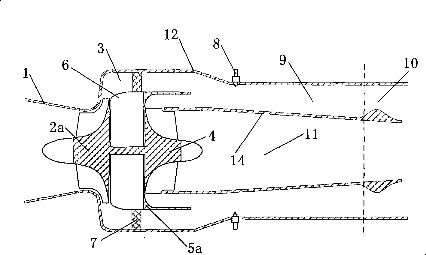
[0036] Such as figure 2 As shown, it includes an intake device 1, a centrifugal compressor 2a, a diffuser buffer chamber 3, a radial turbine 4, a fixed guide 5a, a diversion casing 6, an intake valve 7, an ignition system 8, and a multi-pipe detonation Chamber 9, nozzle 10, inner runner 11, engine casing 12 and inner ring wall 14. Along the airflow direction of the engine, the air intake device 1 is located at the forefront of the engine housing 12, and the centrifugal compressor 2a is located in the engine housing 12, downstream of the air intake device 1 and arranged coaxially with the air intake device 1; the centrifugal compressor 2a It is connected with the radial turbine 4 through a common shaft, and the turbine disc of the radial turbine 4 is upstream, and its blades rush downstream; the guide casing 6 is located between the centrifugal compressor 2a and the radial turbine 4, and the outer edge of its upstream end surface The size is the same as the maximum outer dime...

Embodiment 2

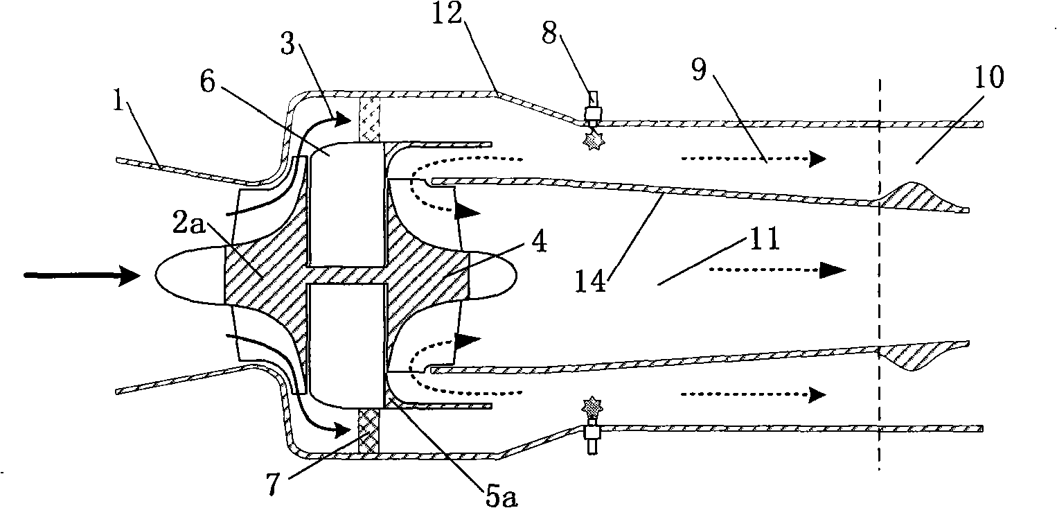
[0039]As shown in Figure 3, it consists of an air intake device 1, a centrifugal compressor 2a, a diffuser buffer chamber 3, a radial turbine 4, a rotary guider type I 5b, a guide casing 6, an ignition system 8, a multi-pipe explosion The shock chamber 9, the nozzle 10, the inner runner 11, the engine casing 12, and the gear transmission system 13 are composed. Along the airflow direction of the engine, the air intake device 1 is located at the forefront of the engine housing 12, and the centrifugal compressor 2a is located in the engine housing 12, downstream of the air intake device 1 and arranged coaxially with the air intake device 1; the centrifugal compressor 2a It is connected with the radial turbine 4 through a common shaft, and the turbine disk of the radial turbine 4 is upstream, and its blades rush downstream; the guide casing 6 is located between the centrifugal compressor 2a and the rotary guider I type 5b, and its upstream end surface The size of the outer edge i...

Embodiment 3

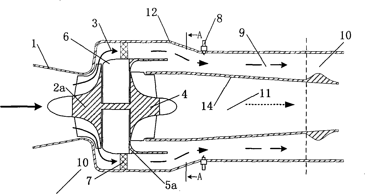
[0041] As shown in Figure 4, it consists of an air intake device 1, a centrifugal compressor 2a, a diffuser buffer chamber 3, a radial turbine 4, a rotary guider II type 5c, a guide casing 6, an ignition system 8, a multi-pipe explosion The shock chamber 9, the nozzle 10, the inner runner 11, the engine casing 12, and the gear transmission system 13 are composed. Along the airflow direction of the engine, the air intake device 1 is located at the forefront of the engine housing 12, and the centrifugal compressor 2a is located in the engine housing 12, downstream of the air intake device 1 and arranged coaxially with the air intake device 1; the centrifugal compressor 2a It is connected with the radial turbine 4 through a common shaft, and the turbine disk of the radial turbine 4 is upstream, and its blades rush downstream; the guide casing 6 is located between the centrifugal compressor 2a and the rotary guider I type 5b, and its upstream end surface The outer edge size is equ...


PUM


Abstract

The invention discloses a turbine combined pulse detonation engine (PDE). An air inlet device is positioned at the front tip of an engine shell; a gas compressor is positioned at the lower reaches of the air inlet device and is coaxial with the air inlet device; the gas compressor is coaxial with a radial turbine; a flow-guide casing is a smooth transition case between the gas compressor and the radial turbine; a guider is positioned between the flow-guide casing and the radial turbine; an inlet valve is positioned between the flow-guide casing and the inner wall of the engine shell; a diffusion cushion chamber ranges from the lower reaches of the gas compressor to the upper reaches of the inlet valve; a multi-tube detonation chamber is positioned at the lower reaches of the inlet valve; the outer annular wall surface of the multi-tube detonation chamber is part of the engine shell and the inner annular wall surface forms an inner annular wall; an inner flow passage is positioned at the lower reaches of the radial turbine; an ignition system is an ignition device of the multi-tube detonation chamber and the exit of the multi-tube detonation chamber is connected with a nozzle. The PDE is no longer than the length corresponding to the maximum external profile diameter of the gas compressor, thus greatly reducing coupling of detonation circulation and turbine operation, having high working frequency and conducing to power extraction.

Description

technical field [0001] The invention relates to the technical field of engines, in particular to a pulse detonation engine. Background technique [0002] The discovery of detonation waves can be traced back to the end of the 18th century. Compared with deflagration waves, the propagation speed of detonation waves can reach several kilometers per second, and at the same time, extremely high gas pressure (greater than 15 to 55 atmospheres) and gas temperature (greater than 2800K), according to the traditional CJ ​​theory, the CJ knock point is the minimum point of entropy increase, which means that the propulsion system based on detonation combustion will have an advantage in thermal cycle efficiency, so since the 1940s, Various institutions are competing to study detonation engines. In the exploration and research stage of more than 60 years, various types of detonation engines have appeared. The current research hotspots in this field mainly focus on pulse detonation engines...

Claims


Application Information

Patent Timeline
IPC IPC(8): F02C3/04F02C3/05F02C3/06
Inventor 邱华严传俊范玮郑龙席
Owner NORTHWESTERN POLYTECHNICAL UNIV
Why Eureka
Try Eureka