
Method for precisely forming copper-nickel alloy flange pipes

A copper-nickel alloy, precision molding technology, applied in the direction of metal extrusion, metal processing equipment, metal extrusion dies, etc., can solve the problems of reducing oxide scale thickness, low production efficiency, shortening heating time, etc., to save waiting time , Improve production efficiency and reduce energy consumption

Active Publication Date: 2009-09-02
725TH RES INST OF CHINA SHIPBUILDING INDAL CORP
View PDF0 Cites 14 Cited by
  • Summary
  • Abstract
  • Description
  • Claims
  • Application Information

AI Technical Summary

Problems solved by technology

[0005] In order to solve the above problems, the present invention provides a precision forming method for copper-nickel alloy flange pipe fittings, which changes the existing simple electric furnace heating method, adopts intermediate frequency induction furnace heating, shortens the heating time, reduces the thickness of oxide skin, and redesigns the forming mold at the same time. Control the processing allowance, so that the raw material utilization rate of the copper-nickel alloy flange is increased by more than 10% on the existing basis, and the production efficiency of the copper-nickel alloy flange product is greatly improved, the production energy consumption is reduced, and the copper-nickel alloy is better solved. The problems of low raw material utilization rate and low production efficiency of the flange play a role in promoting the further improvement of the related technical level of the shipbuilding industry and ocean engineering industry

Method used


Image

  • Method for precisely forming copper-nickel alloy flange pipes
  • Method for precisely forming copper-nickel alloy flange pipes
  • Method for precisely forming copper-nickel alloy flange pipes

Examples


Embodiment 1

[0032] Embodiment 1: The precision forming method of making B10 copper-nickel alloy flange pipe fittings of DN50 specification

[0033] According to the length required by the DN50 specification, the tube blanks are cut on the sawing machine, the power of the induction coil is adjusted to 30KW by the medium frequency induction heater through the power supply, and the pushing frequency is 1 piece / 30 seconds. Put it in, heat it to 900℃~980℃ by the sensor, and push it out at a frequency of 1 piece / 30 seconds. The heated tube blank is installed on the lower mold of the 315T hydraulic press, and the upper mold is fixed on the lower end of the pressure rod of the hydraulic press. The positioning ring is installed on the base, and the lower mold and the core rod are first installed in the positioning ring, the lower mold is positioned by the outer mold, and the outer mold is fixed by the pressure ring and the nut; the lower mold, the outer mold, and the bottom plane of the core rod ar...

Embodiment 2

[0034] Embodiment 2: The precision forming method of making B10 copper-nickel alloy flange pipe fittings of DN80 specification

[0035] According to the length required by the DN80 specification, cut the tube blanks on the sawing machine, adjust the power of the induction coil to 40KW through the power supply of the intermediate frequency induction heater, and push the material at a frequency of 1 piece / 30 seconds. Put it in, heat it to 900℃~980℃ by the sensor, and push it out at a frequency of 1 piece / 30 seconds. The heated tube blank is installed on the lower mold of the 315T hydraulic press, and the upper mold is fixed on the lower end of the pressure rod of the hydraulic press. The positioning ring is installed on the base, the lower mold and the core rod are first installed in the positioning ring, the lower mold is positioned by the outer mold, and the outer mold is fixed by the pressure ring and the nut; the bottom plane of the lower mold, the outer mold and the core rod...

Embodiment 3

[0036] Embodiment 3: The precision molding method of making the B10 copper-nickel alloy flange pipe fitting of DN100 specification

[0037] According to the length required by DN100 specifications, the tube blanks are cut on the sawing machine, the power of the induction coil is adjusted to 50KW through the power supply of the intermediate frequency induction heater, and the pushing frequency is 1 piece / 40 seconds. Put it in, heat it to 900℃~980℃ by the sensor, and push it out at the frequency of 1 piece / 40 seconds. The positioning ring is installed on the base, the lower mold and the core rod are first installed in the positioning ring, the lower mold is positioned by the outer mold, and the outer mold is fixed by the pressure ring and the nut; the bottom plane of the lower mold, the outer mold and the core rod are close At the upper end of the base, the base and the positioning ring are connected by T-shaped blocks and bolts; the heated tube blank is set on the lower mold, a...


PUM


Abstract

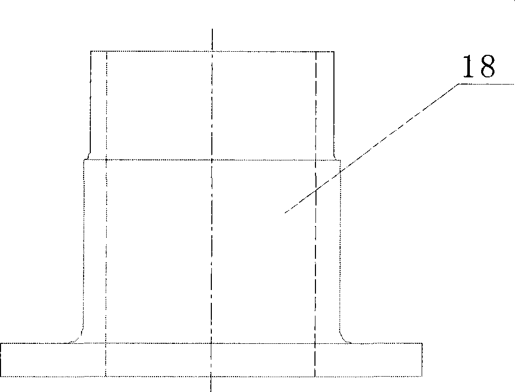
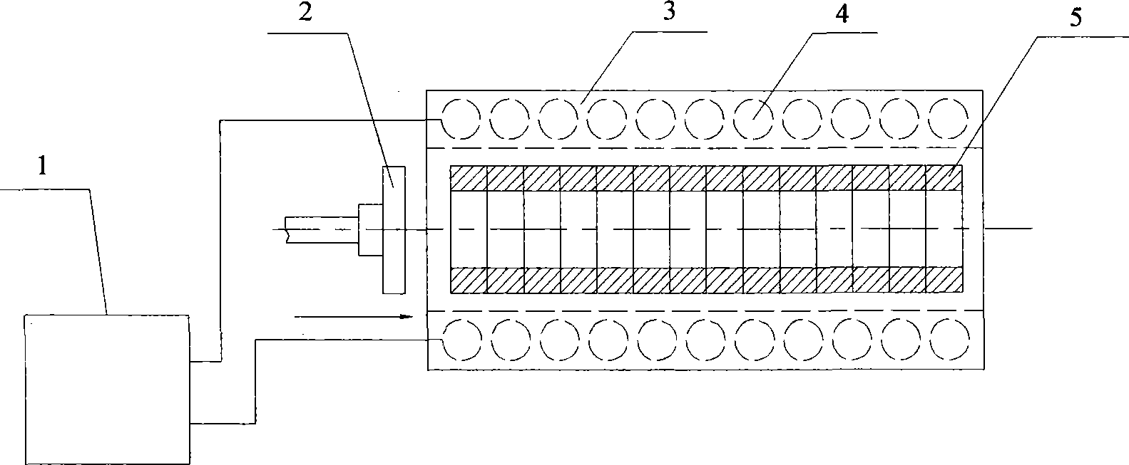
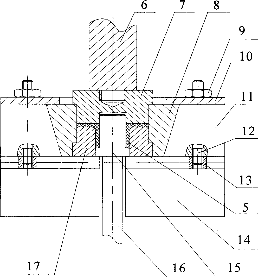
The invention provides a method for precisely forming copper-nickel alloy flange pipes, comprising the following steps of blanking, heating, forming and machining. Firstly, a tube blank 5 is cut on a sawing machine and then arranged in a heater 3; the power of an induction coil 4 is adjusted between 20KW to 100KW by a power supply 1; and the tube blank 5 is pushed into a sensor with the frequency of 1-2 blanks per minute and heated to the temperature of 900-980 DEG C for 0.5-1 minute. An upper die 7 is fixedly arranged at the lower end of a presser bar 6 of a special oil hydraulic press; a locating ring 11 is arranged on a base 14; a lower die 17 and a core bar 15 are loaded firstly; an external die 8 is positioned; a pressing ring 10 and a nut 9 are fixed; the bottom surfaces of the lower die, the external die and the core bar are closely leaned against the upper end of the base and are connected with the locating ring by a T-shaped block 13 and a bolt 12; the tube blank is sleeved on the lower die; the upper die moves downwards and extrudes the tube blank directly so as to be formed; subsequently, the upper die moves upwards and is disconnected with the tube blank; and the formed tube blank is processed as a qualified copper-nickel alloy flange pipe 18 according to technical requirements and surface roughness. The utilization ratio of the tube blank is improved by 10% and the energy consumption is reduced.

Description

technical field [0001] The invention belongs to the technical field of metal processing methods, in particular to a precision forming method for a copper-nickel alloy flange pipe fitting. Background technique [0002] Copper-nickel alloy pipes and pipe accessories have excellent corrosion resistance, anti-marine fouling and other comprehensive properties. They are ideal materials for replacing copper and stainless steel in seawater environments. They are widely used in shipbuilding and marine engineering at home and abroad. Adoption, in which the flange occupies a large proportion in the copper-nickel alloy pipe fittings. [0003] At present, due to equipment and cost constraints, domestic copper alloy pipe fitting manufacturers mostly adopt die-casting method for production of flange products, the production technology is relatively backward, and the product quality is unstable. The copper-nickel alloy flange products of our company adopt the hot extrusion molding process....

Claims


Application Information

Patent Timeline
IPC IPC(8): B21C23/02B21C29/00B21C31/00B21C23/21B21C25/02B21C35/02B21C23/01
Inventor 史鑫付利国赵国超
Owner 725TH RES INST OF CHINA SHIPBUILDING INDAL CORP
Learn More