Rock deforming and cracking three-dimensional dynamic testing system based on fiber strain sensing
An optical fiber strain, three-dimensional dynamic technology, applied in the direction of applying stable tension/pressure to test the strength of materials, measuring devices, using optical devices, etc. question
- Summary
- Abstract
- Description
- Claims
- Application Information
AI Technical Summary
Problems solved by technology
Method used
Image
Examples
Embodiment 1
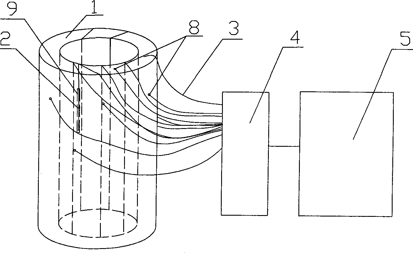
[0020] Example 1: figure 1 Among them, the test piece 1 is cylindrical, and its outer surface and end surface are respectively provided with a number of micro-holes 8, and the inner wall, outer surface and end surface of the cylinder of the test piece 1 are also provided with a number of long micro-grooves 9, and the fiber grating sensor 2 are respectively laid in the microhole 8 and the long micro groove 9, and evenly arranged on the inner surface of the cylinder of the test piece 1; the fiber grating sensor 2 arranged on the outer surface and end surface of the test piece 1 is sealed and Fixed to ensure the effective coupling between the fiber grating sensor 2 and the surface of the rock specimen 1, the fiber grating sensor 2 is connected to the optical switch 4 through the optical fiber 3, and the optical switch 4 is connected to the optical fiber demodulation instrument 5. The fiber grating sensor 2 in the microhole 8 is mainly used to test the strain change in the directi...
Embodiment 2
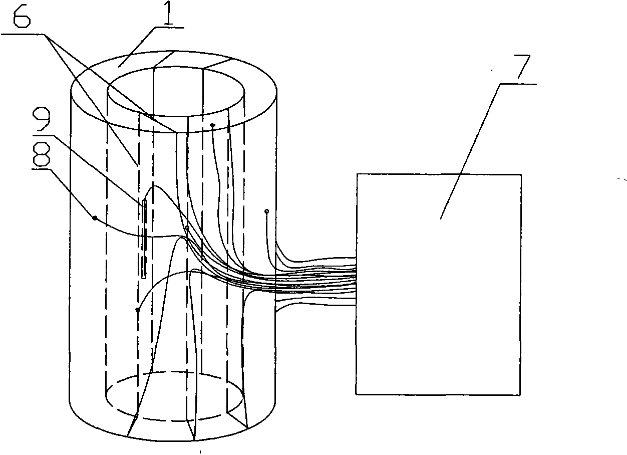
[0021] Embodiment 2: as figure 2 As shown, the test piece 1 is cylindrical, and the outer surface and end surface of the test piece 1 are provided with a number of micropores 8, and the inner wall, outer surface and end surface of the test piece 1 are provided with a number of long micro-grooves 9, and the long-period The grating 6 is laid on the inner surface of the cylinder and in the microholes 8 and elongated micro-grooves 9 on the inner wall, outer surface and end face of the cylinder. One end of the long-period grating 6 is a broadband light source, and the other end is connected to a spectrum analyzer 7 for Analyze the transmission spectrum of a long period grating. The long-period grating 6 in the microhole 8 is mainly used to test the strain change in the direction of the internal horizontal (that is, the X and Y directions); To test the strain change in the vertical (Z direction), the long-period grating 6 in the long micro-groove 9 on the end face is mainly used t...
Embodiment 3
[0022] Embodiment 3: The test piece 1 is square, and the outside of the test piece 1 is provided with several microholes 8 and some long micro-grooves 9, and the long-period grating 6 is laid in the microholes 8 and the long-strip micro-grooves 9, and the long-period grating One end of 6 is a broadband light source, and the other end is connected to a spectrum analyzer 7 for analyzing the transmission spectrum of the long-period grating.
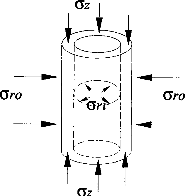
[0023] In the present invention image 3 Indicates the direction of the pressure exerted by the triaxial press on the test piece, the test piece is placed in a sealed pressure chamber, and the upper and lower ends of the test piece are under pressure σ z , the inside of the test piece is filled with high-pressure oil and sealed to cause an outward pressure σ inside the test piece rl , after the outer surface of the specimen is sealed by the external high-pressure oil, an inward pressure σ is generated ro .
[0024] Figure 4 It is a proc...
PUM
 Abstract
Description
Claims
Application Information
 - R&D
- Intellectual Property
- Life Sciences
- Materials
- Tech Scout
- Unparalleled Data Quality
- Higher Quality Content
- 60% Fewer Hallucinations
Browse by: Latest US Patents, China's latest patents, Technical Efficacy Thesaurus, Application Domain, Technology Topic, Popular Technical Reports.
© 2025 PatSnap. All rights reserved.Legal|Privacy policy|Modern Slavery Act Transparency Statement|Sitemap|About US| Contact US: help@patsnap.com


