Inductor and manufacturing method thereof

A technology of inductance and devices, which is applied in the field of inductance devices and their manufacture, and core components of power conversion, can solve the problems of reducing product life, device temperature rise, copper resistance increase, etc., to prolong service life and reduce temperature rise , copper resistance and copper loss reduction effect

Inactive Publication Date: 2009-09-02
清流县鑫磁线圈制品有限公司
View PDF0 Cites 21 Cited by
  • Summary
  • Abstract
  • Description
  • Claims
  • Application Information

AI Technical Summary

Problems solved by technology

The coil frame is an injection-molded integrated structure. The coil of the inductance device with the above-mentioned shape of the magnetic core must use a coil frame, and the inner hole of the middle winding post of the coil frame and the matching surface of the middle column of the magnetic core are an all-encompassing structure. There are thickness requirements for processing, and the thickness requirement is generally greater than 0.5mm, otherwise the quality of the produced skeleton (especially the wall thickness) is difficult to guarantee. There must be a certain gap of about 0.5mm, and one side is larger and the other is smaller, which will further increase the gap between the bobbin and the center column of the magnetic core. The sum of the two is about 1mm, so the circumference of the winding on the bobbin will increase. Large, increasing the length and material of the coil enameled wire, and the coils on the inductance device are generally hundreds or thousands of turns, which increases the copp

Method used


Image

  • Inductor and manufacturing method thereof
  • Inductor and manufacturing method thereof
  • Inductor and manufacturing method thereof

Examples


Embodiment 1

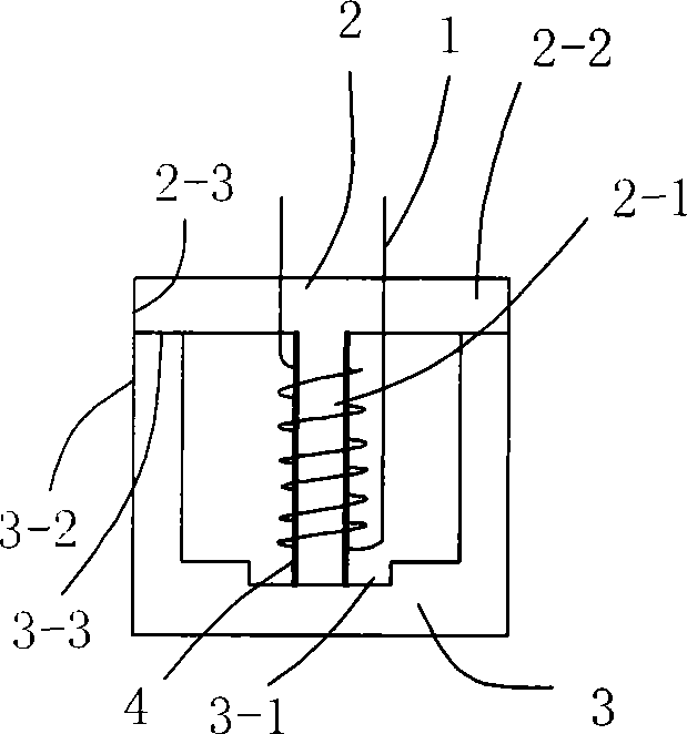
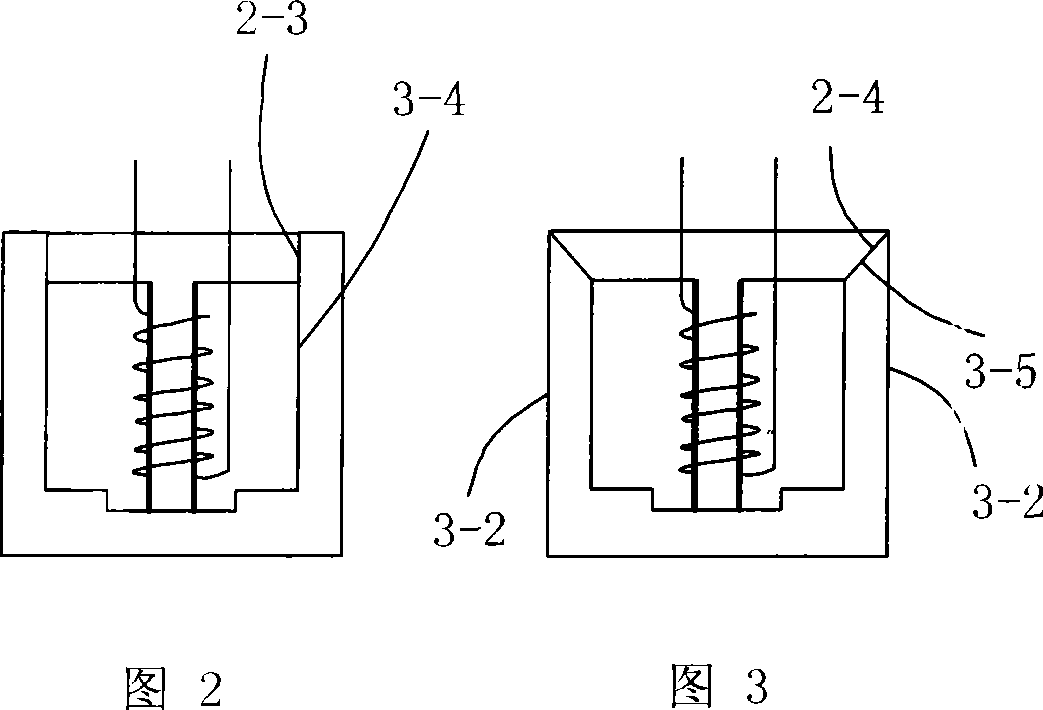
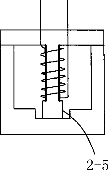
[0037] An embodiment of an inductance device in which the shape of the central column magnetic core is T-shaped and the shape of the side column magnetic core is U-shaped, see Figure 1 to Figure 6 , the inductance device includes a central column magnetic core, a side column magnetic core and a coil 1, the shape of the central column magnetic core is a T-shaped magnetic core 2, the shape of the side column magnetic core is a U-shaped magnetic core 3, and the U-shaped There is a groove 3-1 in the middle of the inner side of the side column magnetic core, and the end of the vertical magnetic core column 2-1 of the T-shaped central column magnetic core is inserted into the groove in the middle of the inner side of the U-shaped side column magnetic core, and the T-shaped The two ends of the transverse magnetic core column 2-2 of the center column magnetic core are docked with the ports of the U-shaped side column magnetic core to form a Japanese-shaped closed magnetic circuit core...

Embodiment 2

[0047] An embodiment of an inductance device in which the shape of the central column magnetic core is an I-shaped magnetic core, and the shape of the side column magnetic core is two inline magnetic cores, see Figure 7 to Figure 10 , the inductance device includes a central column magnetic core, a side column magnetic core and a coil, the shape of the central column magnetic core is an I-shaped magnetic core 5, and the shape of the side column magnetic core is two inline magnetic cores 6, two Two in-line magnetic cores are respectively docked with the two ports of the I-shaped central column magnetic core to form a day-shaped closed magnetic circuit core body. The butt joint distance (magnetic circuit air gap) of each butt surface is adjusted according to the magnetic saturation requirements. The distance is between 0 and 5mm, the coil is wound and arranged on the central column 5-1 of the I-shaped central column magnetic core, an insulating layer is arranged between the coil...

Embodiment 3

[0055] An embodiment of an inductance device in which the shape of the central column magnetic core is a straight-shaped magnetic core, and the shape of the side column magnetic core is a square-shaped magnetic core, see Figure 11 to Figure 21 , the inductance device includes a central column magnetic core, a side column magnetic core and a coil. The column magnetic core is placed in the middle of the square-shaped side column magnetic core and docked with it to form a day-shaped closed magnetic circuit core body. The butt joint distance (magnetic circuit air gap) of each butt surface is adjusted according to the magnetic saturation requirements. The adjusted distance is 0 5mm, the coil is wound on the inline-shaped central column magnetic core, and an insulating layer is arranged between the coil and the inline-shaped central column magnetic core, and the thickness of the insulating layer is less than 0.5mm.

[0056] in:

[0057] refer to Figure 11 As shown, the square-sh...


PUM

PropertyMeasurementUnit
Thicknessaaaaaaaaaa
Thicknessaaaaaaaaaa
Thicknessaaaaaaaaaa

Abstract

The invention relates to an inductor and a manufacturing method thereof. The inductor comprises a closed magnetic loop magnetic core and a coil, wherein the closed magnetic loop magnetic core consists of non-E-type magnetic core bodies and takes the shape of a Chinese character 'ri'. The manufacturing method of the inductor comprises the following steps of firstly arranging an insulating layer on a magnetic core column which needs winding of the magnetic core at the central column, with the thickness less than 0.5 mm, and then according to the required number of circles, sequentially winding by using single-stranded enameled wires or multi-stranded intertwisted enameled wires; after winding the enameled wires, butt jointing the magnetic core at the central column and the magnetic core at the side column into the closed magnetic loop magnetic core body taking the shape of the Chinese character 'ri'; and tightly binding up the outer side of the magnetic core body by using insulating tapes, so as to lead the magnetic core at the central column and the magnetic core at the side column to be butt jointed tightly and firmly. The invention has the beneficial effects that: compared with the traditional inductor with the coil, the single-stranded enameled wire length of the winding coil is reduced, the number of windings is greatly reduced, and the copper material is saved by over 10 percent; simultaneously, the diffusion magnetic flux can be minimized so as to decrease the copper resistance and copper loss of the inductor, and the temperature rise of the inductor is decreased accordingly, thus saving both materials and electrical energy, and prolonging the service life of the product simultaneously.

Description

technical field [0001] The invention relates to electrical components, in particular to an inductance device and a manufacturing method thereof. The inductance device is a core component of power conversion for green lighting and power supply parts of various electronic equipment. Background technique [0002] Traditional coil inductance devices are generally composed of EE combined magnetic core or EI combined magnetic core with coil frame (skeleton) wound with enameled wire. The coil frame is an injection-molded integrated structure. The coil of the inductance device with the above-mentioned shape of the magnetic core must use a coil frame, and the inner hole of the middle winding post of the coil frame and the matching surface of the middle column of the magnetic core are an all-encompassing structure. There are thickness requirements for processing, and the thickness requirement is generally greater than 0.5mm, otherwise the quality of the produced skeleton (especially t...

Claims


Application Information

Patent Timeline
IPC IPC(8): H01F27/24H01F27/30H01F27/32H01F41/02H01F17/04
CPCH01F27/324H01F27/306H01F37/00H01F27/263
Inventor 黄思忠陈限育林金城薛文碧
Owner 清流县鑫磁线圈制品有限公司
Why Eureka
Try Eureka