Fly ash pipe gas flow crushing process

A technology of airflow crushing and conveying pipelines, which is applied in the direction of grain processing, etc., can solve the problems of high energy consumption and high power of driving motors, and achieve the effects of simple system, reduced investment and reduced production costs

Inactive Publication Date: 2009-09-09
HUNAN ELECTRIC POWER POWDERED COAL ASH COMPLEX UTILIZATION DEV
View PDF0 Cites 6 Cited by
  • Summary
  • Abstract
  • Description
  • Claims
  • Application Information

AI Technical Summary

Problems solved by technology

Due to the heavy weight of the ball mill and the metal ball itself, the required driving motor power is also very large, ranging from several hundred to more than one thousand kilowatts, and the energy consumption is extremely high.

Method used


Image

  • Fly ash pipe gas flow crushing process
  • Fly ash pipe gas flow crushing process
  • Fly ash pipe gas flow crushing process

Examples


Embodiment Construction

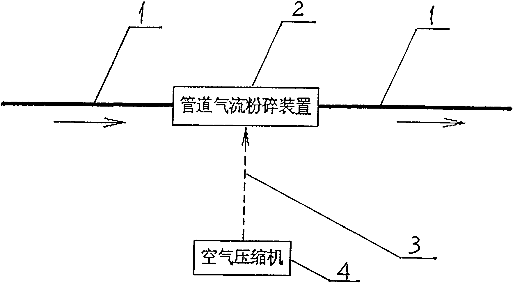
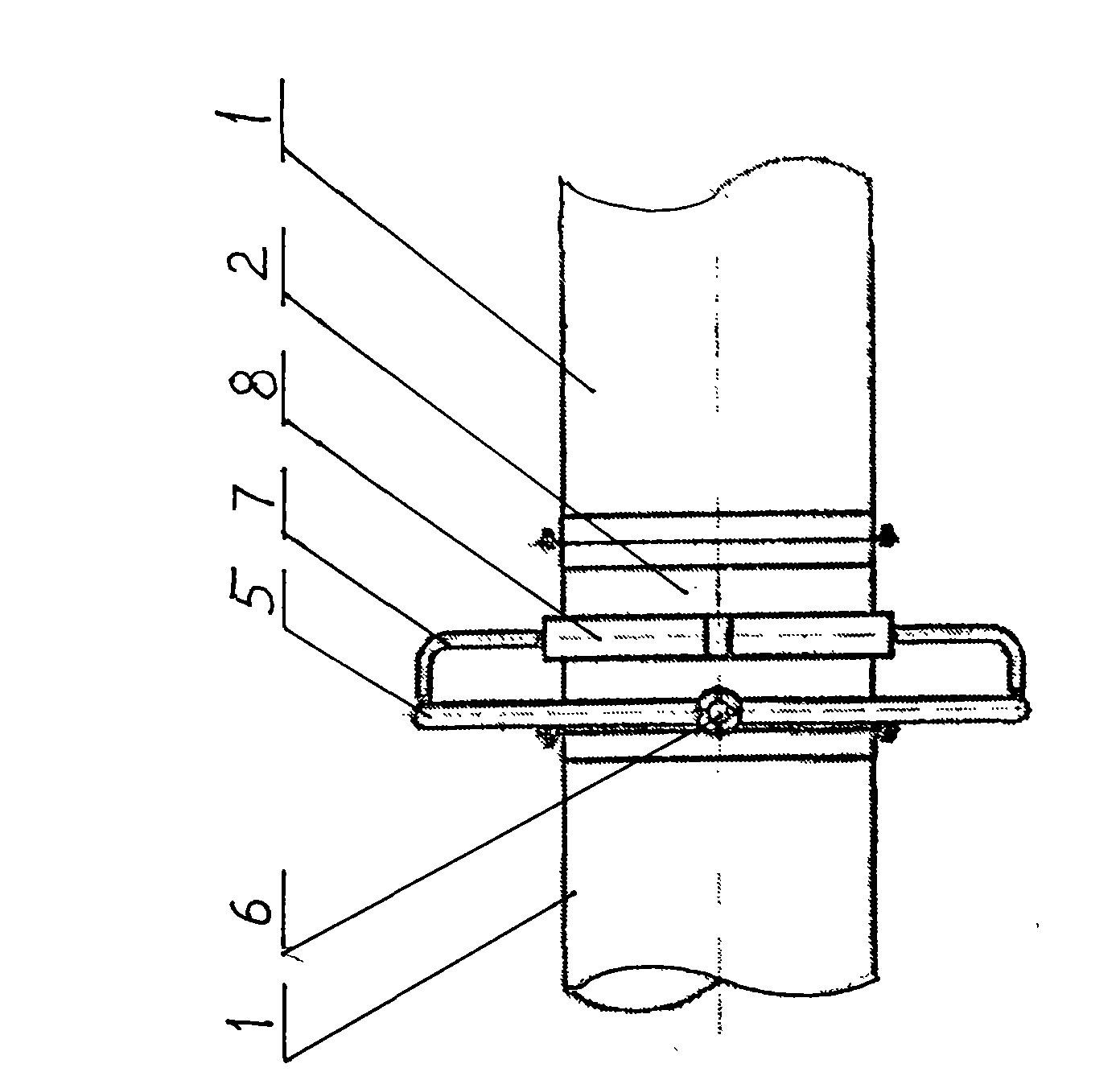
[0038] Referring to the accompanying drawings, the present invention completely abandons the grinding process of the ball mill, and directly installs a pipeline airflow crushing device in series on the way of fly ash transportation, that is, in a certain section of the original fly ash airflow conveying pipeline. The high-speed airflow makes the fly ash collide with each other at a high speed to realize the ultra-fine crushing of the fly ash during the transportation. The pipeline airflow crushing device 2 is the core component of the fly ash airflow conveying pipeline to realize the airflow crushing process. It is mainly composed of compressed air inlet , O-ring pipe, radial branch pipe, spray gun ring, nozzle, connecting flange, and bracket. The air compressor produces compressed gas with a pressure of 0.6-0.8Mpa, which enters the pipeline airflow crushing device, and then passes through the O-ring pipe. And the radial branch pipe enters the spray gun ring, and finally sprays...


PUM


Abstract

The invention discloses a fly ash pipe gas flow crushing process. Pipe gas flow crushing devices are serially connected in a fly ash gas flow pipe, and ultrahigh-speed gas flows externally applied by the pipe gas flow crushing devices allow the fly ash to mutually collide at a high speed to realize ultrafine crushing of the fly ash during transmission. The ultrahigh-speed gas flows externally applied by the pipe gas flow crushing devices are compressed air sprayed into the fly ash gas pipe in form of ultrahigh-speed gas flows through an O-shaped annular pipe, branch pipes, a spray gun ring and nozzles. The process obviously saves energy and is simple in process, low in investment, small in equipment space occupation, good in sealing and environment-protection performance, large in fine powder amount, and low in production cost.

Description

Technical field: [0001] The invention relates to a material crushing process, in particular to an airflow crushing process of a fly ash conveying pipeline. Background technique: [0002] The traditional fly ash crushing method is to use a ball mill to grind the fly ash. see Figure 4 The flow chart of the fly ash grinding process of the ball mill is shown. The main body of the ball mill is cylindrical, that is, a rotating cylinder with a diameter of 1 to 3 meters and a length of several meters to more than ten meters. It is hollow inside and placed horizontally on the bearing bush. When grinding, 50% of the space in the cylinder cavity is filled with fly ash and wear-resistant metal balls (several tons to nearly a hundred tons). The cylinder is driven by an external high-power high-voltage motor through a reduction box for low-speed rotation, and the metal balls are thrown The smashing and mutual friction between the fly ash and the fly ash will be finely ground. Because t...

Claims


Application Information

Patent Timeline
IPC IPC(8): B02C19/06
Inventor 石峰管国华
Owner HUNAN ELECTRIC POWER POWDERED COAL ASH COMPLEX UTILIZATION DEV
Why Eureka
Try Eureka