Synchronous range/velocity measurement system based on non-scanning laser radar and CCD camera

A laser radar, scanning-free technology, applied in radio wave measurement systems, measurement devices, camera devices, etc., can solve the problem of inability to obtain motion information, direction and speed, and achieve the effect of simple structure, high precision, and small devices

Inactive Publication Date: 2009-09-09
HARBIN INST OF TECH
View PDF0 Cites 33 Cited by
  • Summary
  • Abstract
  • Description
  • Claims
  • Application Information

AI Technical Summary

Problems solved by technology

[0003] In order to solve the problem that the existing non-scanning laser radar can only obtain the distance information of the object, but cannot obtain the mot

Method used


Image

  • Synchronous range/velocity measurement system based on non-scanning laser radar and CCD camera
  • Synchronous range/velocity measurement system based on non-scanning laser radar and CCD camera
  • Synchronous range/velocity measurement system based on non-scanning laser radar and CCD camera

Examples


specific Embodiment approach 1

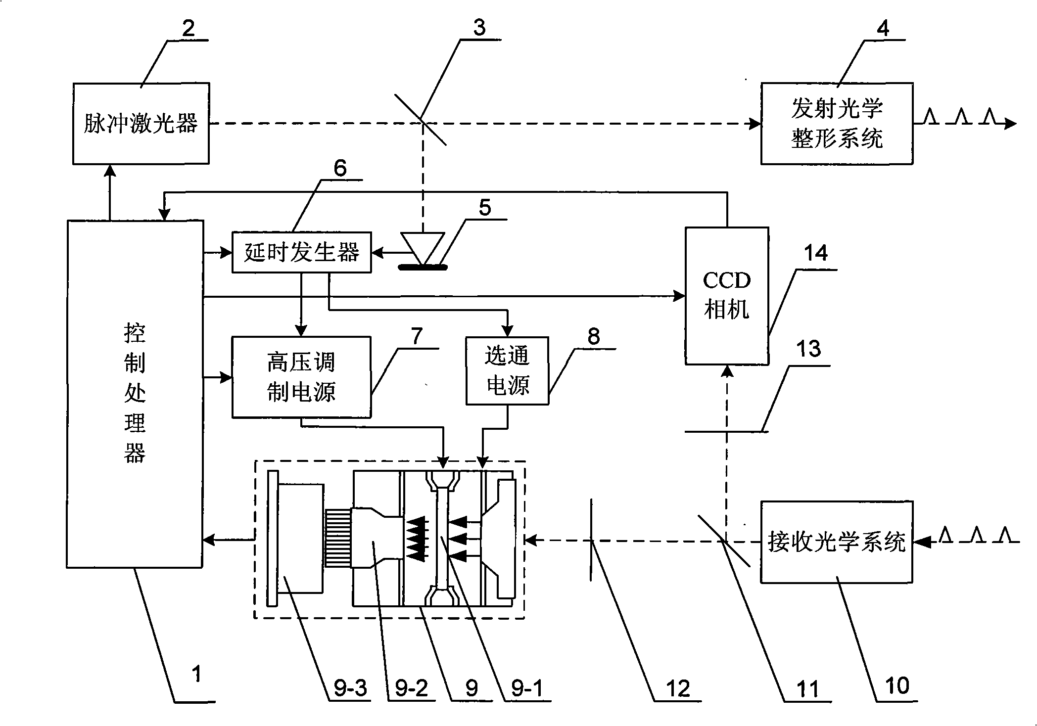
[0011] Specific implementation mode 1: Combination figure 1 To describe this embodiment, this embodiment consists of a non-scanning lidar, a control processor 1, a first optical splitter 3, a PIN decoder 5, a delay generator 6, a high-voltage modulation power supply 7, a strobe power supply 8, and a second optical splitter 11. Narrow-band filter 12, band-stop filter 13 and CCD camera 14; non-scanning lidar is composed of pulse laser 2, transmitting optical shaping system 4, ICCD area detector 9 and receiving optical system 10;

[0012] The laser beam emitted by the pulse laser 2 is split by the first beam splitter 3 and then irradiated on the receiving surface of the transmitting optical shaping system 4 and PIN decoder 5 respectively, and the laser beam irradiated on the transmitting optical shaping system 4 is shaped and then irradiated On the target, the echo pulses reflected by the target are received by the receiving optical system 10. After being converged by the receiving ...

specific Embodiment approach 2

[0014] Specific implementation manner two: combination figure 1 This embodiment is described. The difference between this embodiment and the first embodiment is that the ICCD area array detector 9 is composed of a microchannel plate 9-1, a fluorescent screen 9-2 and a CCD 9-3; the microchannel plate 9-1, The phosphor screen 9-2 and the CCD 9-3 are sequentially arranged on the same horizontal optical axis. Other components and connection modes are the same as the first embodiment.

specific Embodiment approach 3

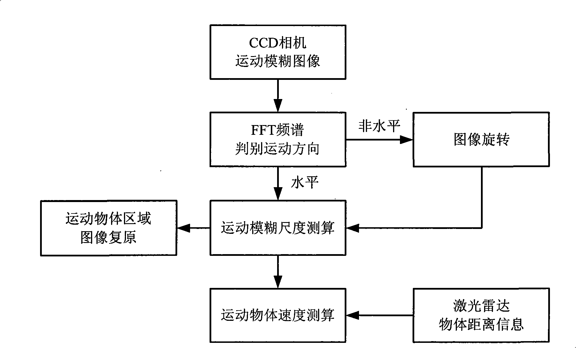
[0015] Specific implementation mode three: combination figure 2 This embodiment is described. The difference between this embodiment and the second embodiment is that the control processor 1 is used to trigger the pulse laser 2 and the high-voltage modulation power supply 7 to generate a high-voltage modulation signal, and it is also used to control the delay generator 6 to generate a delay. The signal is also used to set the exposure time of the CCD camera 14 and trigger the pulsed laser 2 to emit two pulses with time intervals during the said exposure time, and trigger the microchannel of the ICCD area array detector 9 while emitting the pulses The gain modulation of the board 9-1, the two pulses correspond to different modulation gain methods; and it is used to process the image information transmitted from the ICCD area detector 9 and the CCD camera 14 to obtain a range image. The processing process is as follows:

[0016] Firstly, the FFT spectrum determines the direction of ...


PUM


Abstract

A synchronous range/velocity measurement system based on a non-scanning laser radar and a CCD camera is disclosed. The invention relates to the field of laser radar measurement and solves the problem that the current non-scanning laser radar can only obtain range information of an object, but is incapable of obtaining motion information. The non-scanning laser radar in the inventive system is composed of two parts including transmission and reception, the transmission part comprises a pulse laser and a transmission optical shaping system, and the reception system comprises an ICCD imager and a reception optical system; in the inventive system, the CCD camera is also combined and shares the reception optical system with the non-scanning laser radar, and a band elimination filter is added in front of the CCD camera so as to receive light signals; on condition that the increased complexity of the system structure is avoided as much as possible, the range information and the motion information of motion objects are synchronously obtained in a very short exposure time; the system is mainly applied to the measurement of the motion objects.

Description

Technical field [0001] The invention relates to the field of lidar measurement. Background technique [0002] Scanning range imaging lidar is one of the main directions of today's lidar development. However, the existing scanless lidar can only obtain the distance information of the object, but cannot obtain the speed information of the moving object. However, laser Doppler velocimeters and radar Doppler velocimeters are expensive, independent in structure, and large in size, so it is difficult to use them in conjunction with non-scanning lidar. All of these limit the ability of non-scanning lidar to obtain the target's movement information (direction and speed), and further limit its application range. Summary of the invention [0003] In order to solve the problem that the existing scanless lidar can only obtain the distance information of the object, but cannot obtain the motion information (direction and speed), the present invention proposes a synchronous distance measureme...

Claims


Application Information

Patent Timeline
IPC IPC(8): G01S17/08G01C11/02
Inventor 孙秀冬许元男赵远刘丽萍张宇靳辰飞吴杰陈锺贤
Owner HARBIN INST OF TECH
Why Eureka
Try Eureka