Diesel engine cylinder fuel-cut oil-saving system with twin-pressure charging system and pressure relief device

A technology of pressure relief device and supercharging system, which is applied in mechanical equipment, engine control, machine/engine, etc., can solve the influence of supercharger performance, compression work, pumping loss, influence on combustion of working cylinder and Thermal efficiency, affecting the reliability of the supercharger, etc., to improve the spray quality, ensure normal work and reliability, and reduce frictional resistance.

Inactive Publication Date: 2009-09-16
SHANGHAI JIAO TONG UNIV
View PDF1 Cites 15 Cited by
  • Summary
  • Abstract
  • Description
  • Claims
  • Application Information

AI Technical Summary

Problems solved by technology

Its shortcoming is that it does not take into account the impact on the performance of the supercharger after some cylinders of the supercharged diesel engine stop working, as well as the loss of compression work and pumping gas, etc.
On the one hand, this is because when some cylinders of the supercharged diesel engine stop working, the work of the supercharger will be affected, the temperature difference between the exhaust gases of each cylinder will increase, and the possibility of surge will increase, which not only affects the reliability of the supercharger, but also Affects the combustion and thermal efficiency of

Method used


Image

  • Diesel engine cylinder fuel-cut oil-saving system with twin-pressure charging system and pressure relief device
  • Diesel engine cylinder fuel-cut oil-saving system with twin-pressure charging system and pressure relief device
  • Diesel engine cylinder fuel-cut oil-saving system with twin-pressure charging system and pressure relief device

Examples


Embodiment 1

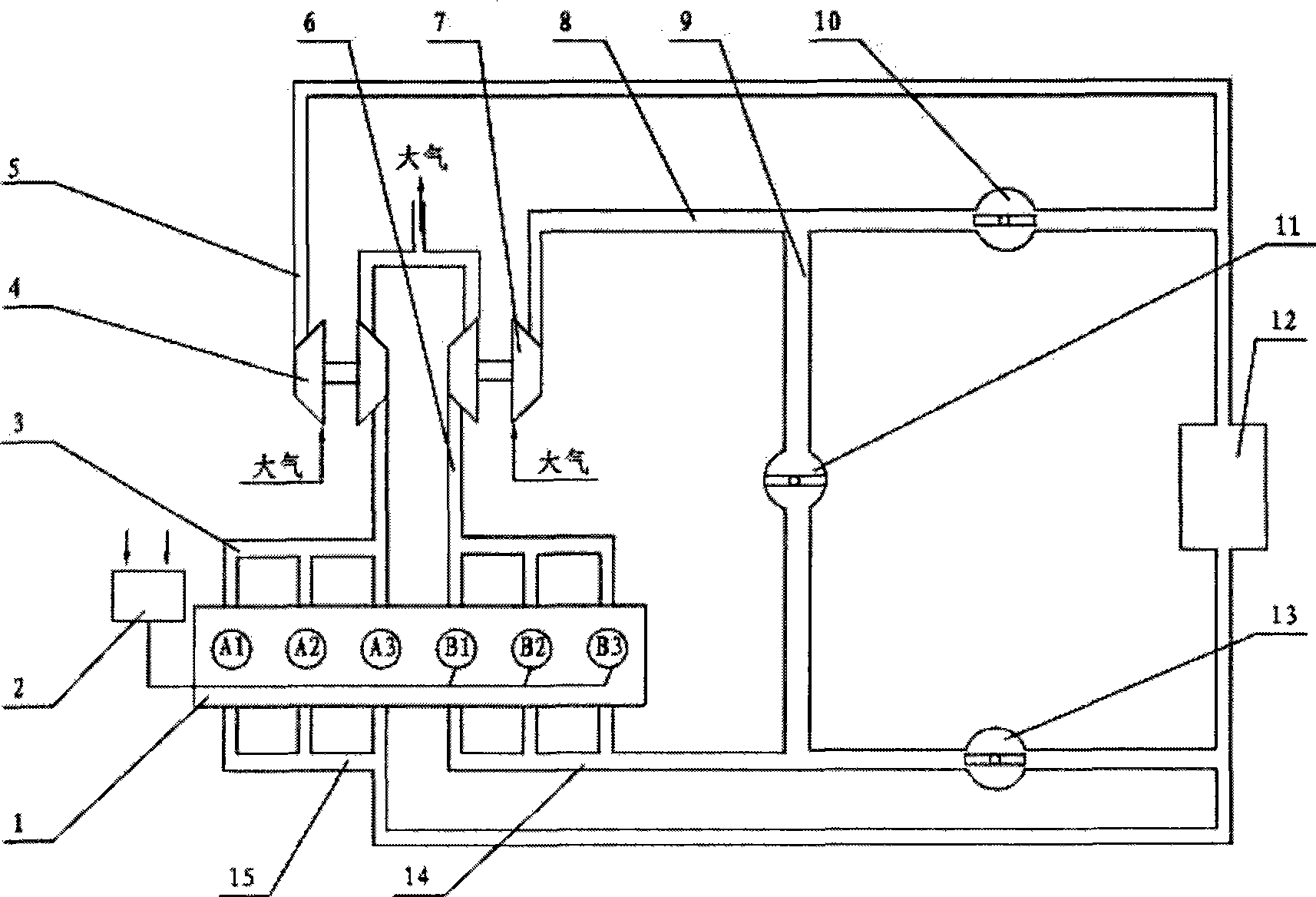
[0026] Such as figure 1 As shown, taking an in-line six-cylinder diesel engine as an example, this embodiment involves a diesel engine deactivation fuel-saving system with double superchargers and cylinder pressure relief devices, including a diesel engine 1, a set of cylinder pressure relief devices 2, a first Supercharging system, second supercharging system, intercooler 12. Diesel engine 1 is divided into A group of cylinders (including A1, A2, A3 cylinders) and B group of cylinders (including B1, B2, B3 cylinders) according to the requirements of the firing sequence, and the independent first supercharging system and the second supercharging system are used respectively. Connected to form two sets of booster systems and working cylinders that can operate independently. Cylinder pressure relief device 2 is respectively connected with the inlets of group B cylinders (including B1, B2 and B3 cylinders).

[0027] The first supercharging system includes a first exhaust manifo...

Embodiment 2

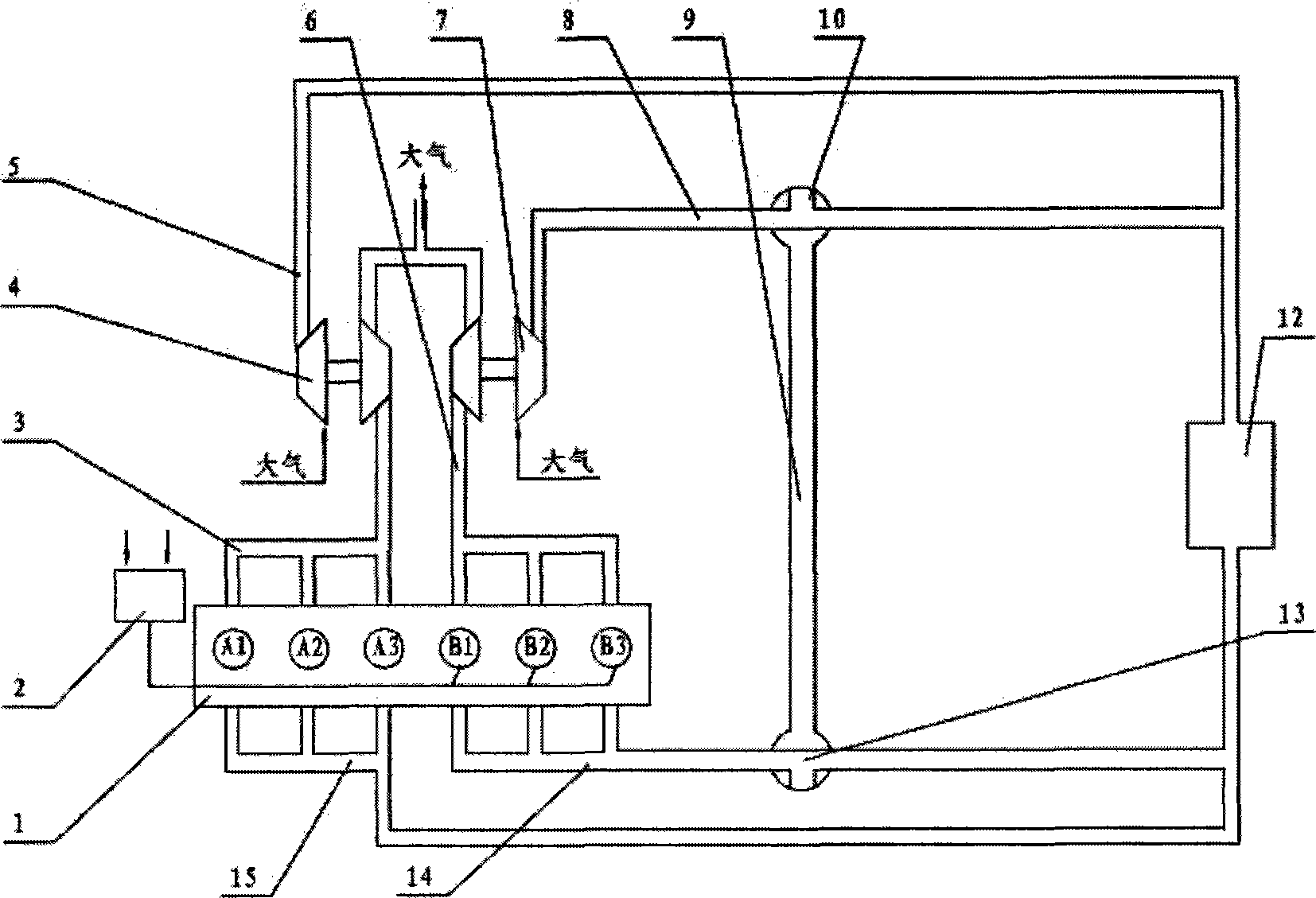
[0032] Such as image 3 As shown, it is the working condition of the fuel-saving system of the diesel engine with double supercharger and cylinder pressure relief device with three-way valve structure under high load conditions, including diesel engine 1, a set of cylinder pressure relief device 2, the first booster Compression system, second supercharging system, intercooler 12. Diesel engine 1 is divided into two groups of cylinders according to the requirements of the firing sequence, which are respectively connected with independent first supercharging system and second supercharging system to form two groups of supercharging systems and working cylinders that can operate independently. Cylinder pressure relief device 2 is respectively connected with B group cylinder inlet.

[0033] The structure of the first pressurization system is the same as that of Embodiment 1.

[0034] In this embodiment, the valve adopts a three-way valve, and the three-way valve is used to contr...

Embodiment 3

[0038] Figure 5 It is a V-type 12-cylinder diesel engine (taking the constant-pressure supercharging system as an example) under high-load conditions that adopts a butterfly valve structure with double superchargers and cylinder pressure relief devices. The working conditions of the diesel engine deactivation fuel-saving system. It includes a diesel engine 1, a set of cylinder pressure relief device 2, a first supercharging system, a second supercharging system, and an intercooler 12. Diesel engine 1 is divided into two groups of cylinders according to the firing order, wherein group A cylinders include cylinders A1, A2, A3, A4, A5, and A6, and group B cylinders include cylinders B1, B2, B3, B4, B5, and B6. The first supercharging system and the second supercharging system are connected to form two groups of independently operating supercharging systems and working cylinders. Cylinder pressure relief device 2 is respectively connected with B group cylinder inlet. The booste...


PUM


Abstract

The invention relates to a diesel engine cylinder fuel-cut oil-saving system with a twin-pressure charging system and a pressure relief device. The diesel engine cylinder fuel-cut oil-saving system comprises a multi-cylinder diesel engine, a first pressure charging systems, a second pressure charging system, a charge air cooler and a set of cylinder pressure relief device, wherein cylinders in the multi-cylinder diesel engine are divided into two groups according to the sequence of ignition: the first group of cylinders are connected with the first pressure charging system, while the second group of the cylinders are connected with the second pressure charging system; the cylinder pressure relief device is connected with the second group of the cylinders; and the charge air cooler is connected with the two groups of the cylinders through the first pressure charging system and the second pressure charging system respectively. The diesel engine cylinder fuel-cut oil-saving system can increase fuel injection capacity of one group of the cylinders by cylinder fuel-cut, thereby improving the quality of injection and atomization of the system, and improving thermal efficiency; two independent superchargers are adopted, so that interference on non-working cylinders on the superchargers when a supercharged diesel is in fuel cut can be overcome, thereby ensuring normal work of the working cylinders; and friction work of the non-working cylinders are greatly reduced by the cylinder pressure relief cylinder, thereby further reducing fuel consumption.

Description

technical field [0001] The invention relates to a fuel-saving system in the technical field of diesel engines, in particular to a cylinder-stop fuel-saving system of a diesel engine with a double booster system and a pressure relief device. Background technique [0002] When the engine is partially loaded, cutting off the oil supply of some cylinders and increasing the load of other working cylinders to improve the thermal efficiency of the engine is one of the effective measures for engine fuel saving. This technology is currently mainly used in gasoline engines, usually naturally aspirated multi-cylinder gasoline engines. This method has also been studied and used on diesel engines, but the fuel-saving effect obtained is very limited, so it has not been really applied in batches on supercharged diesel engines. [0003] Through literature search to prior art, it is found that Chinese patent CN86205030U "Diesel Engine Solenoid Valve Cylinder Stop Fuel-Saving Device" propose...

Claims


Application Information

Patent Timeline
IPC IPC(8): F02D13/06
Inventor 冒晓建卓斌王俊席唐航波
Owner SHANGHAI JIAO TONG UNIV
Why Eureka
Try Eureka