Solid electrolytic capacitor

A technology of solid electrolysis and capacitors, which is applied in the direction of electrolytic capacitors, capacitors, capacitor electrodes, etc., can solve the problems of increased cost and decreased material utilization rate, and achieve the effects of simplified manufacturing process, excellent material utilization rate, and increased manufacturing speed

Active Publication Date: 2013-12-25
SANYO ELECTRIC CO LTD
View PDF1 Cites 2 Cited by
  • Summary
  • Abstract
  • Description
  • Claims
  • Application Information

AI Technical Summary

Problems solved by technology

Therefore, a process of forming the pillow member 54 or the irregularity 55 is required, and the corresponding cost increases.
In addition, the pillow member 54 or the irregular piece 55 is formed between the anode lead-out portion 57 and the anode terminal 51 by welding or the like, so that the material yield is lowered due to variation in welding or the like (refer to Patent Document 1).

Method used


Image

  • Solid electrolytic capacitor
  • Solid electrolytic capacitor
  • Solid electrolytic capacitor

Examples


no. 1 approach

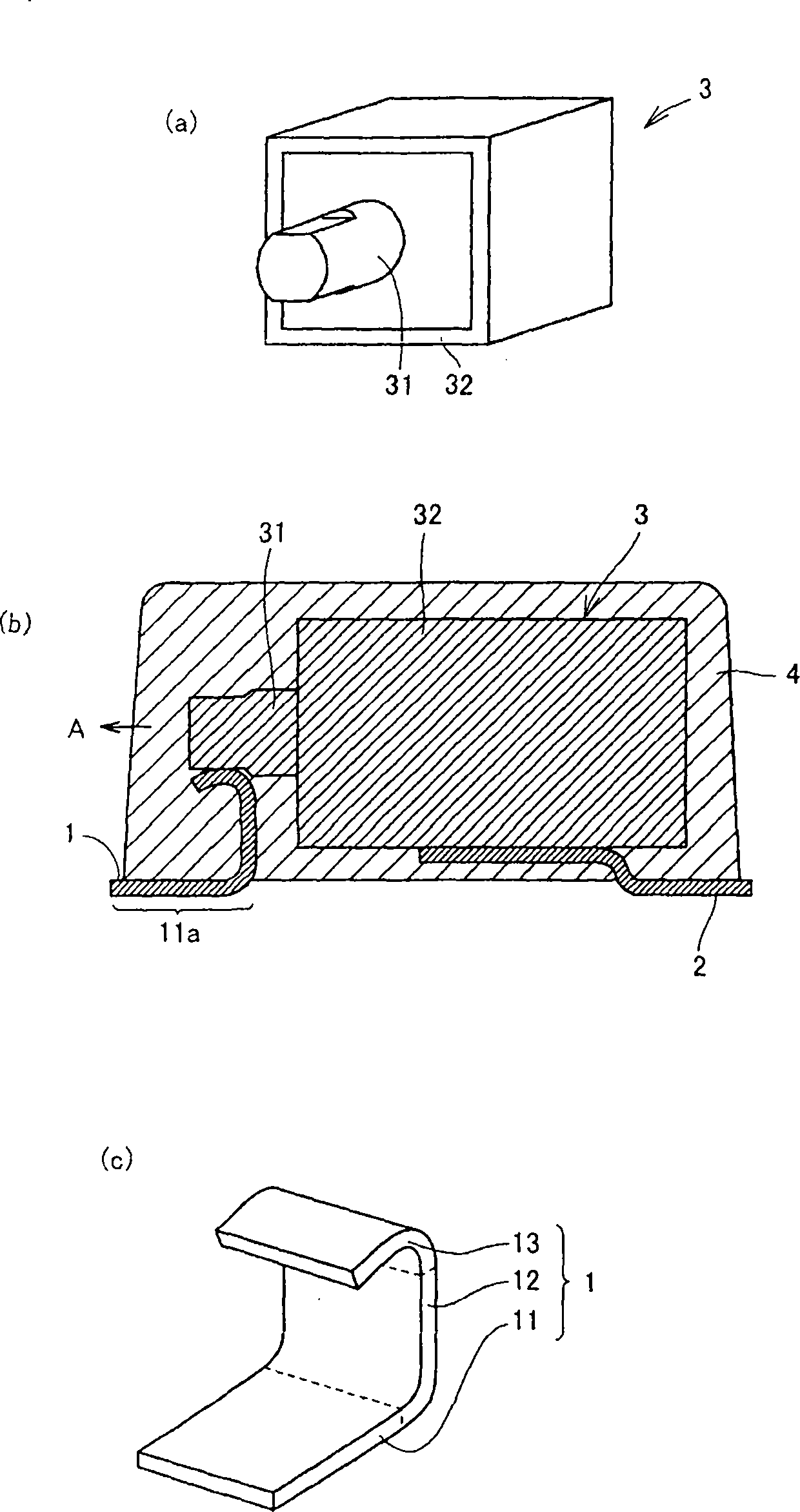
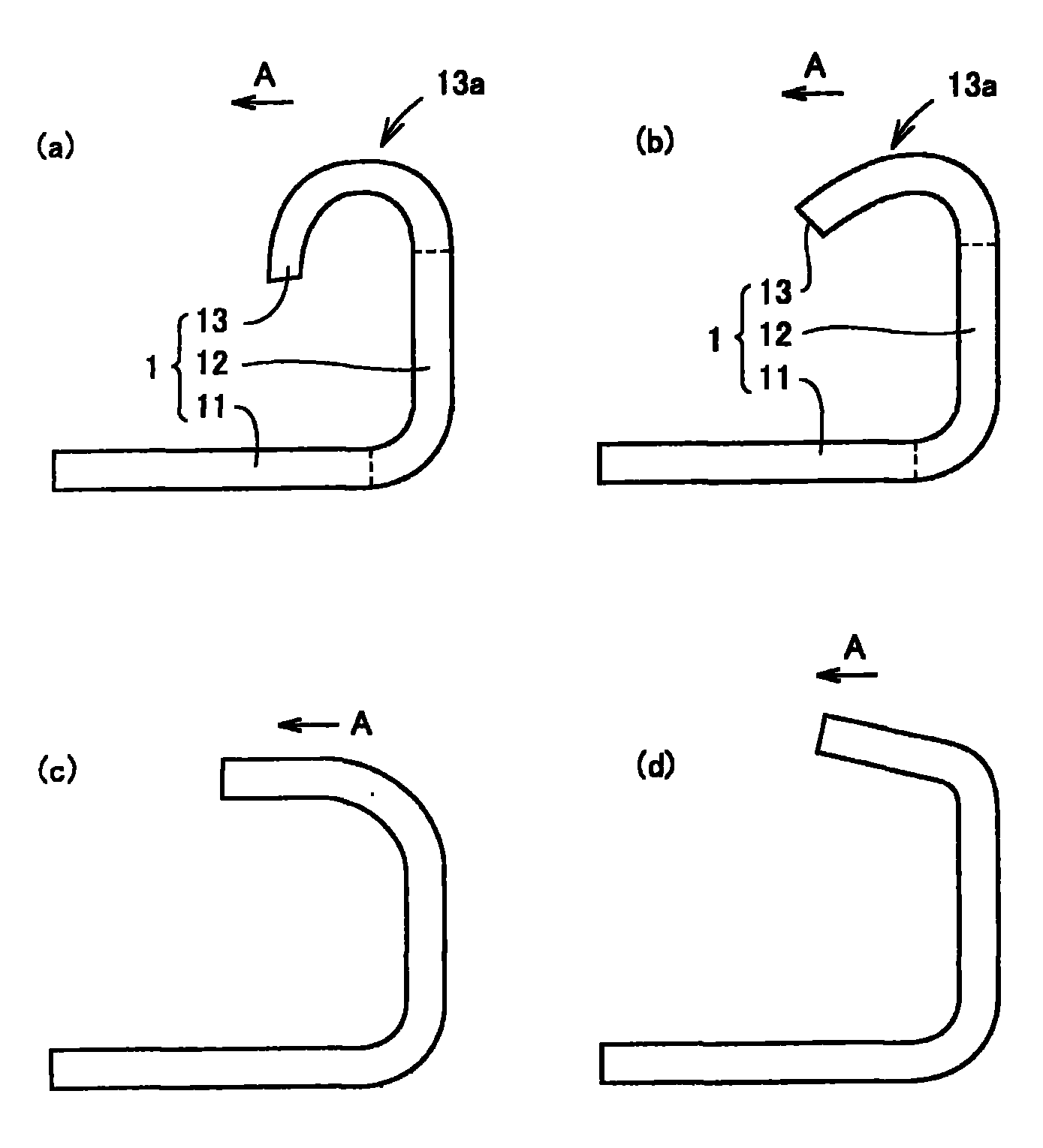
[0018] figure 1 The structure of the solid electrolytic capacitor of this embodiment is illustrated. figure 1 (a) is a perspective view of the capacitor element 3 constituting the solid electrolytic capacitor. like figure 1 As shown in (a), the capacitor element 3 includes an anode lead-out portion 31 and a cathode lead-out portion 32 , and the anode lead-out portion 31 has a structure protruding from one end face of the capacitor element 3 . In this specification, a capacitor element refers to various solid electrolytic capacitor elements having a structure in which a valve metal is used as an anode, a dielectric film is formed on the surface of the anode metal, and a cathode is formed on the surface of the dielectric film. The solid electrolyte layer, and then the cathode extraction layer is formed on the surface of the solid electrolyte layer. figure 1 (b) is a cross-sectional view showing the structure of the solid electrolytic capacitor of the present embodiment. ...

no. 2 approach

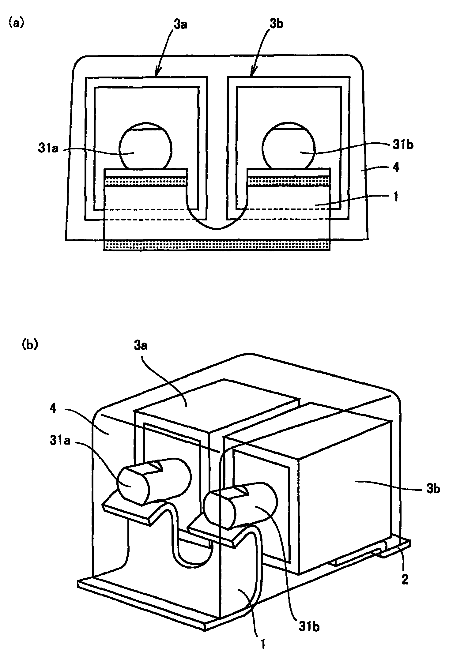
[0029] Image 6 The structure of the solid electrolytic capacitor of this embodiment is illustrated. Image 6 (a) is a side view of the solid electrolytic capacitor when viewed from the protruding direction of the anode lead-out portions 31a, 31b, Image 6 (b) is a perspective view. like Image 6 As shown in (a) of FIG. 2 , two capacitor elements 3 a and 3 b are provided, and the respective anode lead-out portions 31 a and 31 b are connected to one anode lead frame 1 . In this embodiment, unlike the first embodiment, the anode lead-out portions 31a and 31b are cylindrical. In addition, in the present embodiment, the bent portion 13 of the anode lead frame 1 has a slit opened in a direction in which the anode lead-out portions 31a and 31b protrude from the capacitor elements 3a and 3b, and the anode lead-out portions 31a and 31b and the anode lead frame 1 are located in the slit. Seam 13b is connected. Therefore, the anode lead-out portions 31a and 31b are in line contact ...


PUM


Abstract

A solid electrolytic capacitor of the present invention includes: a capacitor element having an anode leading part and a cathode leading part; an anode lead frame connected to the anode leading part and a cathode lead frame connected to the cathode leading part; and an packing resin with which the capacitor element is coated, and the anode leading part protrudes from one end face of the capacitor element. The anode lead frame includes: an anode terminal part having an exposed surface exposed from the packing resin, a rising part connected to the anode terminal part, bent toward the anode leading part located in the upper part of the anode terminal part and extending in the packing resin, and a bent part connected to the rising part and bent along a direction which is parallel to a protruding direction of the anode leading part and connected to the anode leading part.

Description

technical field [0001] The present invention relates to a solid electrolytic capacitor in which a capacitor element is sealed with a sheathing resin such as synthetic resin. Background technique [0002] The solid electrolytic capacitor includes a capacitor element in which a dielectric oxide film and a solid electrolyte layer are formed on an anode body, and a sintered body of a valve metal such as tantalum and niobium is used for the anode body. The dielectric oxide film is formed by anodizing the surface of the anode body, and the solid electrolyte layer is a conductive polymer layer such as polypyrrole formed on the anodic oxide film by chemical compounding or the like. A cathode lead-out portion made of silver or carbon and silver is formed on the solid electrolyte layer, and a valve-action metal anode lead-out portion is formed so as to protrude from one end face of the anode body. Figure 5 It is a figure which shows the structure of the conventional solid electrolyti...

Claims


Application Information

Patent Timeline
Patent Type & Authority Patents(China)
IPC IPC(8): H01G9/012
CPCH01G9/26H01G9/04H01G9/012
Inventor 松冈桂子梅田昌志
Owner SANYO ELECTRIC CO LTD
Why Eureka
Try Eureka