Branchial filter

A filter and filter unit technology, applied in the direction of fixed filter elements, filter separation, chemical instruments and methods, etc., can solve the problems of limited filter area, large space occupation, high energy consumption, etc., to reduce energy consumption and improve treatment capacity, low energy consumption

Inactive Publication Date: 2009-09-23
NANJING INST OF GEOGRAPHY & LIMNOLOGY
View PDF0 Cites 27 Cited by
  • Summary
  • Abstract
  • Description
  • Claims
  • Application Information

AI Technical Summary

Problems solved by technology

This kind of biomass suspension has a low concentration, a large flow rate, and has colloidal or colloid-like amorphous characteristics. The specific gravity of the biomass contained is close to that of water. The use of traditional separation methods is inefficient and easy to cause blockage
Belt screen machines, rotary screens, and vibrating inclined screens are more suitable, but there are still problems such as large space occupation, limited filtration area, small capacity, and high energy consumption.
Especially after the emergence of cyanobacteria pollution in lakes in my country, various cyanobacteria collection ships came into being. Generally, filtration with a sieve, inclined plane filtration or vibrating inclined sieve is used for primary separation. The filtration area is strictly limited by the deck area of ​​the carrier ship. Most of the separation capacity is tens of cubic meters of water per hour, which is far from meeting the needs of cyanobacteria disaster control in large lakes such as Taihu Lake, Chaohu Lake, and Dianchi Lake.

Method used


Image

  • Branchial filter
  • Branchial filter
  • Branchial filter

Examples


Embodiment Construction

[0038] The present invention carries out engineering application according to the following steps:

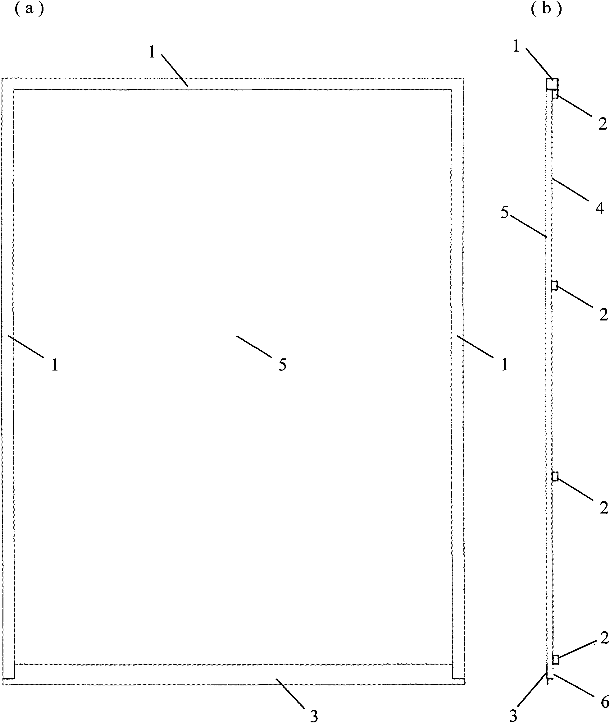
[0039] (1) Arrange the main liquid collecting tank and the liquid inlet main pipe along the center line of the site. The bottom of the general liquid collecting tank is embedded in the ground, and the liquid inlet main pipe is installed at a height of about 1m above the general liquid collecting tank.

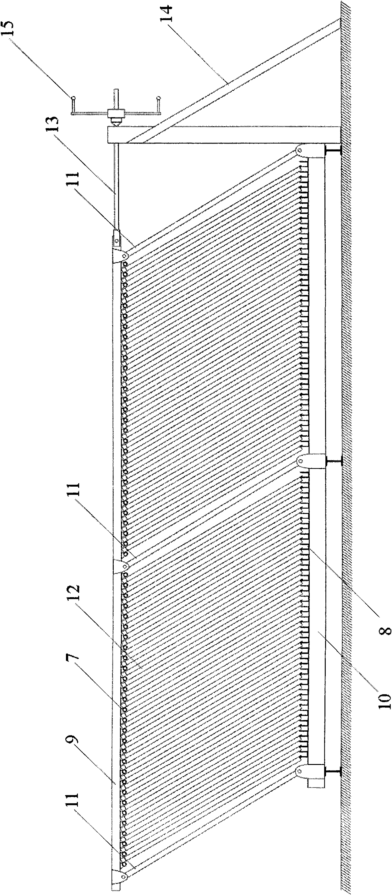
[0040] (2) Install the gill filter unit support frame, spray pipe and small liquid collection tank on both sides, and install the liquid inlet branch pipe.

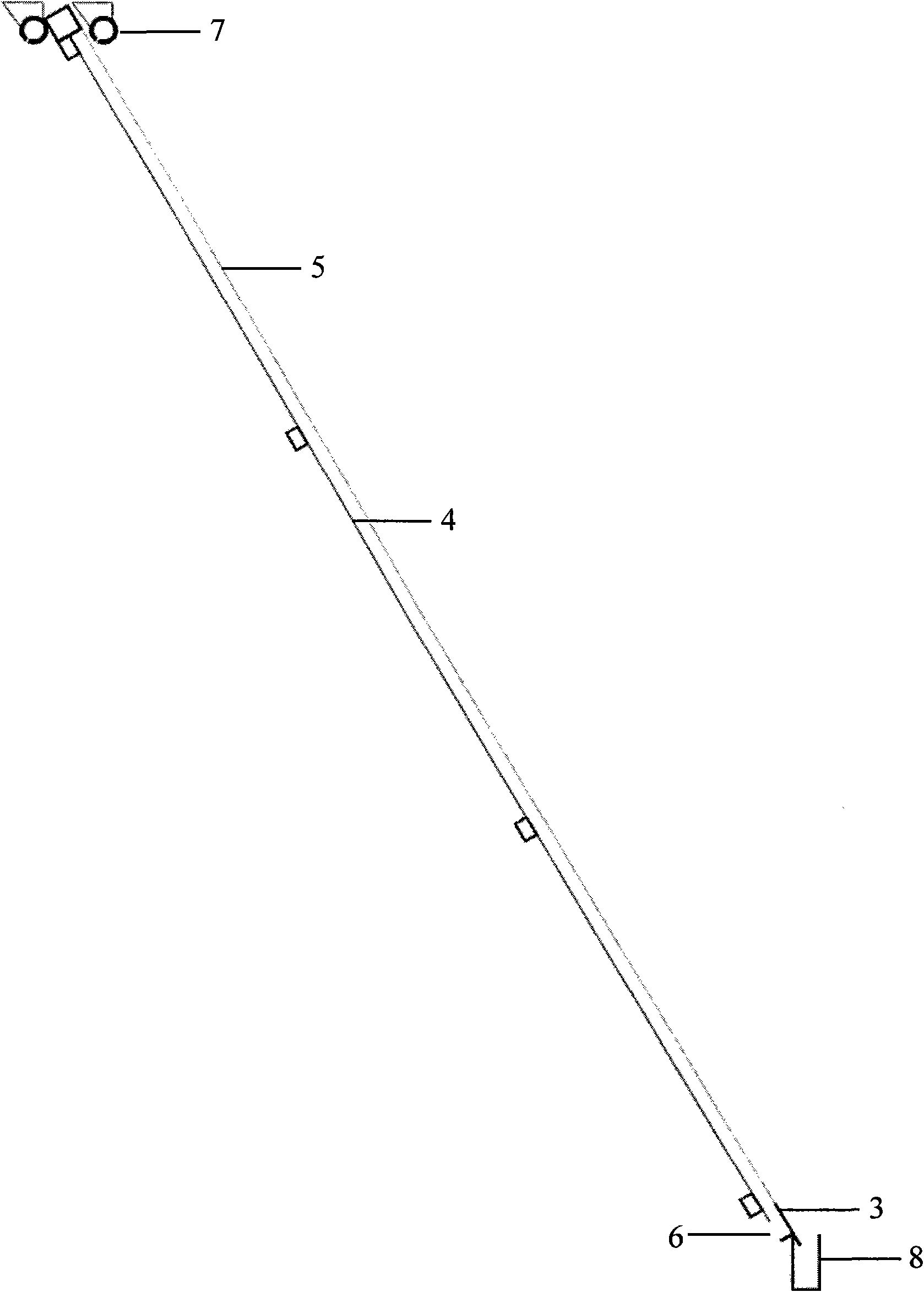
[0041] (3) Make unit inclined screens, and insert all unit inclined screens into the support frame from both sides.

[0042] (4) Open the main gate valve of the liquid inlet and adjust to an appropriate flow rate (the design flow rate of the gill filter).

[0043] (5) According to the filtering conditions, adjust the inclination of the gill filter unit to achieve the best filtering effect.

[0044] (6) Close the gate valv...


PUM


Abstract

The invention relates to a high-densification slope filter which is developed by imitating the principle that a chub branchial filters hydroplankton. A group of (100 or more) unit hydra-screens with the thickness of 40mm are densely arranged on a support frame which can adjust inclination degree with a center distance of 100mm, the surface of each unit hydra-screen sprays a stock solution by a spraying pipe arranged on the top of each unit hydra-screen, and a small liquid collection groove arranged on the bottom of each unit hydra-screen collects concentrated solutions on the screen to form a branchial filtering unit; two branchial filtering units are placed in parallel, a liquid collection groove arranged on the lower middle part of a gap between the two branchial filtering units collects concentrated solution from both sides of the small liquid collection groove positioned below each unit hydra-screen, and a main liquid feeding pipe positioned on the upper part of the gap supplies original liquid to the spraying pipe on the top of each unit hydra-screen at the two sides through branched pipes so as to form a branchial filter. The branchial filter works depending on the pressure (about 20kpa), the concentrated solution on the screen is automatically collected through the small liquid collection groove and a total liquid collection groove, then filtered by the screen and finally discharged to the ground. The invention can be used for the primary concentration and filtering of suspending liquid and especially suitable for the primary filtering of a ship borne algae collecting system.

Description

Technical field: [0001] Solid-liquid separation technology. The invention relates to a highly intensive slope filter developed by imitating the principle of gills of silver carp to filter plankton in water, which is suitable for high-flow primary concentrated filtration of low-concentration suspensions, especially for the primary primary concentration and filtration of biomass such as algae particles visible to the naked eye in water bodies separate. Background technique: [0002] In the production of edible algae and the collection and control of algae in natural water bodies, it is necessary to separate algae from lake water or culture fluid at a large flow rate; in food production and biochemical industries, it is often necessary to solidify low-concentration biomass suspensions. - liquid separation. This kind of biomass suspension has a low concentration, a large flow rate, and has colloidal or colloid-like amorphous characteristics. The specific gravity of the biomass...

Claims


Application Information

Patent Timeline
Patent Type & Authority Applications(China)
IPC IPC(8): B01D29/52
Inventor 李文朝杨清心潘继征冯慕华李玲
Owner NANJING INST OF GEOGRAPHY & LIMNOLOGY
Why Eureka
Try Eureka