Full automatic plastic bottle pipe heating blowing machine

A fully automatic, stretch-blow machine technology, applied in the field of plastic machinery, can solve the problems of complex structure, increased volume, and easy failure of the equipment, and achieve the effects of saving heating power, small size change, and reliable action

Inactive Publication Date: 2009-09-23
浙江东方州强塑模实业有限公司
View PDF0 Cites 5 Cited by
  • Summary
  • Abstract
  • Description
  • Claims
  • Application Information

AI Technical Summary

Problems solved by technology

The bottle tube loading mechanism of the existing heating stretch blowing machine generally uses a robot to send the bottle tube to the bottle tube support of the heating stretch blowing machine operating system. Press down-then rise-reverse-turn over 180°-fall, the disadvantage is that three sets of cylinders drive the manipulator, the structure is complex, the action cycle is long, and it must be installed on the side edge of the operating system, which increases the volume of the whole machine, especially The 180°turned parts are easy to damage and have a short service life; the bottle tube heating and conveying mechanism includes the support for installing the bottle tube, the power to drive the bottle tube support, the bottle tube heating operation route, the bottle tube entering the blowing mechanism and the forming bottle. output path etc.
In the prior art, the installation of the bottle tube is to connect the support seat on the outside of the transmission chain. The bottle tube mouth is generally facing downward. Usually, the tube is inserted (sleeved) and taken by hand. The work efficiency is low. Take the tube, take the tube, turn the bottle tube 180°, push it out, and then press the tube down to cover the support rod, so there are many parts and cylinders in the manipulator, the control is very complicated, and it is easy to break down; the power to drive the bottle tube support is Motor and sprocket, the running route of bottle tube heating is a circular route composed of transmission chain and sprocket, and the output of entering the stretch blowing mechanism and forming bottles is also on the circular route of the chain. It will be elongated during the operation, especially after the elongation, the positioning of the stretching and blowing mechanism is not accurate. Second, the circular route composed of the chain and the sprocket makes the heating area of ​​the bottle tube very long, especially for processing multiple bottles at a time. When using a single product, the whole machine is very bulky and takes up a lot of workshops. The third is that the bottle tube needs to stop moving forward when it enters the stretching and blowing stage, that is, the circular motion is intermittent. Generally, a stepping motor is used to drive the sprocket, and the equipment structure is complicated. , large investment and high control requirements; the existing bottle ejection (unloading) mechanism is to take out the formed bottle manually, and its disadvantages are that the operation is troublesome, the labor intensity of the operator is high, and the second is that the hands pollute the bottle, which is unhygienic

Method used


Image

  • Full automatic plastic bottle pipe heating blowing machine
  • Full automatic plastic bottle pipe heating blowing machine
  • Full automatic plastic bottle pipe heating blowing machine

Examples


Embodiment Construction

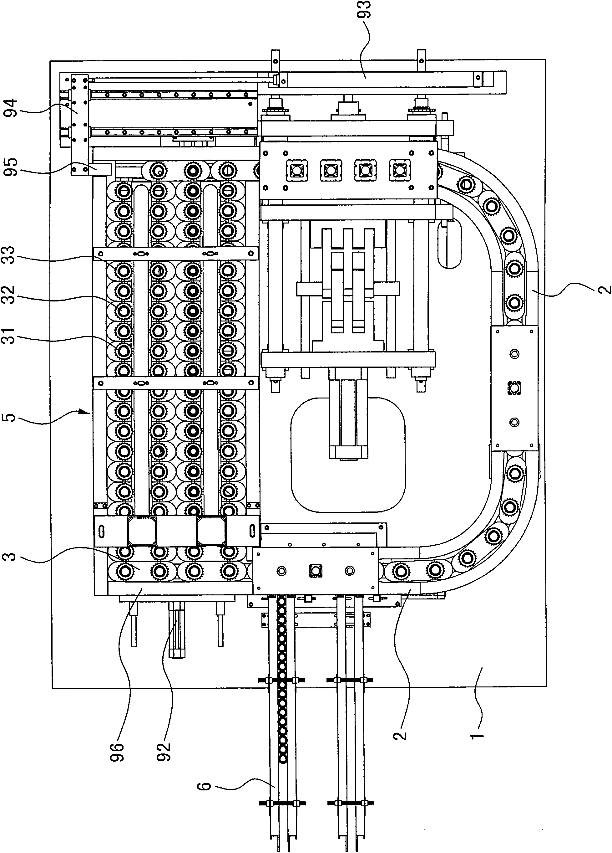
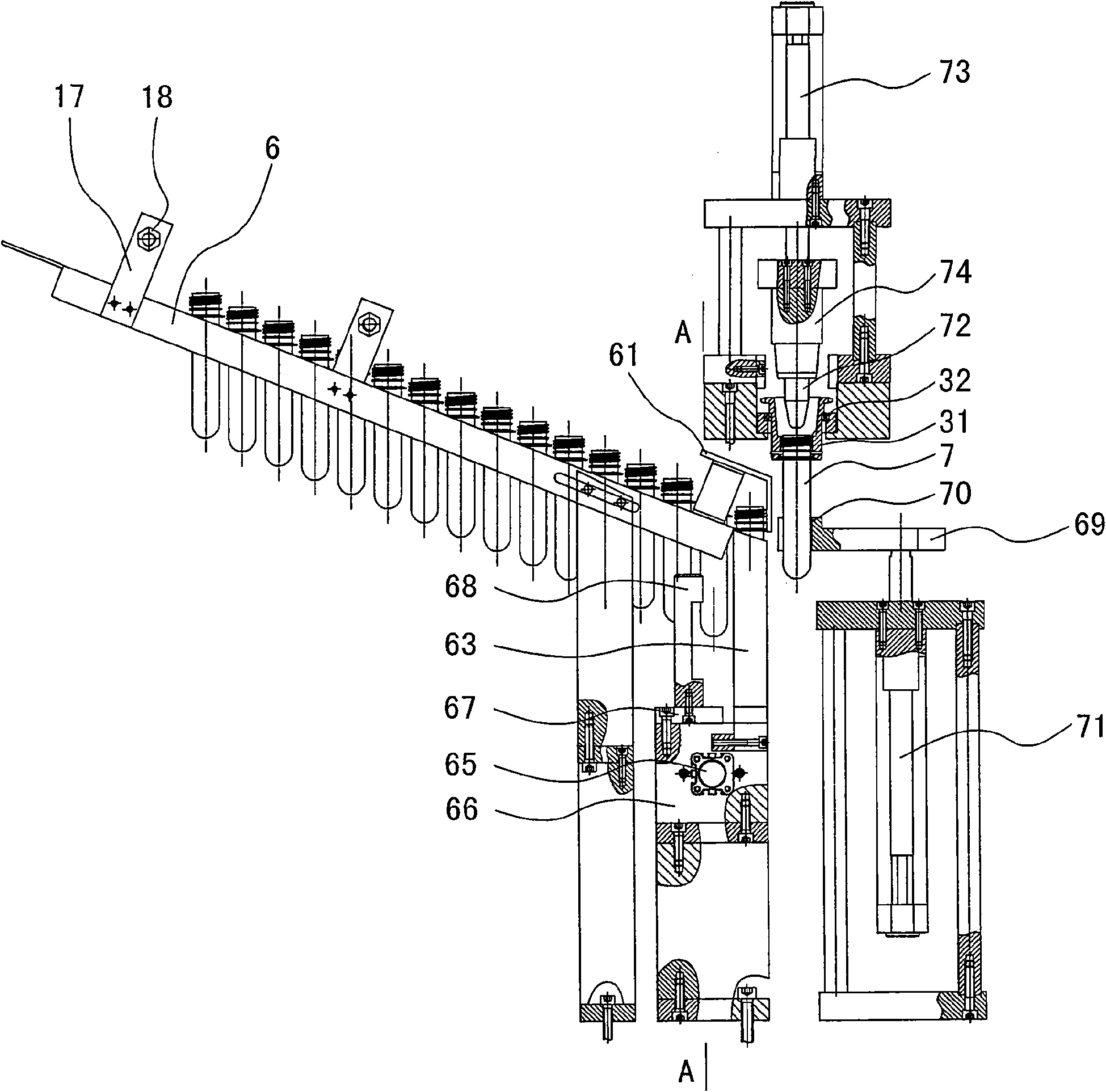
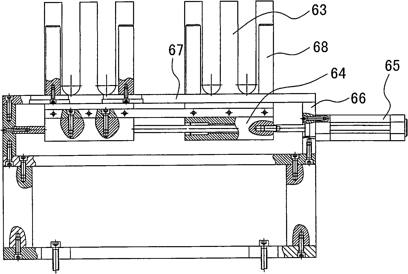
[0013] The invention relates to a fully automatic plastic bottle tube heating and blowing machine, such as Figure 1-Figure 6As shown, it includes a bottle tube feeding mechanism installed on the frame 1, a bottle tube heating and conveying mechanism, a stretch blow molding mechanism and a bottle ejection mechanism. The bottle tube feeding mechanism includes a plastic bottle tube delivery device, a branch tube device, upper tube device and upper tube guiding device, the bottle tube heating conveying mechanism includes a bottle tube conveying track installed on the frame, a bottle tube support is installed in the track, the bottle tube support is driven by power, and the track is divided into The feeding area, the heating area, the stretch blow molding area and the bottle ejection area are characterized in that the pipe delivery device is a sloped slideway 6, and a pipe baffle plate 61 is installed at the exit of the slideway 6; the pipe branching device includes a pipe branch ...


PUM


Abstract

The invention relates to a full automatic plastic bottle pipe heating blowing machine. The heating blowing machine comprises a bottle pipe charging mechanism, a heating conveying mechanism, a blowing mechanism and a bottle leaking mechanism. The charging mechanism comprises a pipe conveying device, a pipe separating device, a pipe feeding device and a guiding device. The heating conveying mechanism comprises a bottle pipe conveying track arranged on a machine frame, and a bottle pipe supporting piece is arranged in the track. The pipe conveying device is an inclined sliding runner which has a pipe retaining plate at the outlet. The pipe separating device comprises a fixed plate and a sliding plate; a pipe separating cylinder arranged on the fixed plate drives the sliding plate; a U-shaped plate is arranged on the sliding plate; and a blowing block is arranged on a bearing plate. The pipe feeding device comprises a pipe feeding plate which has a pipe receiving port; and a pipe feeding cylinder is driven by the pipe feeding plate. The guiding device comprises a guiding cylinder which drives a guiding head. The bottle pipe conveying track is a sliding track. The supporting piece comprises sliders, and rotating shafts are arranged in the sliders. The sliders are driven to move in the sliding track through cylinders including a heating zone driving cylinder and a blowing zone driving cylinder. After entering a heating zone, the sliders are changed into a status of advancing side by side.

Description

technical field [0001] The invention relates to a full-automatic plastic bottle tube heating stretch-blow machine, which belongs to the field of plastic machinery and is mainly used for processing hollow plastic containers such as mineral water bottles and oil bottles. Background technique [0002] Hollow plastic containers such as mineral water bottles and oil bottles are processed by injection stretch blowing. First, plastic raw materials (such as PET, etc.) are injected into bottle tubes by an injection molding machine, and then the bottle tubes are heated by a heater, and then heated by a stretch blowing machine. The final bottle tube stretch blow molding, the automatic heating stretch blow machine is a combination of heater and stretch blow machine on the same machine, which can be divided into bottle tube feeding mechanism, bottle tube heating and conveying mechanism, stretch blow molding mechanism and bottle ejection mechanism. The bottle tube loading mechanism of th...

Claims


Application Information

Patent Timeline
Patent Type & Authority Applications(China)
IPC IPC(8): B29C49/28B29C49/42B29C49/70B29C31/08B29L22/00
Inventor 王自强
Owner 浙江东方州强塑模实业有限公司
Why Eureka
Try Eureka