Method, device and system for inquiring state based on Flash

A state query and state technology, applied in the direction of instrumentation, electrical digital data processing, etc., can solve the problem of resource shortage of Flash controller pins

Active Publication Date: 2009-09-23
HUAWEI TECH CO LTD
View PDF0 Cites 7 Cited by
  • Summary
  • Abstract
  • Description
  • Claims
  • Application Information

AI Technical Summary

Problems solved by technology

In this case, some pins can be saved, but it still cannot fundamenta

Method used


Image

  • Method, device and system for inquiring state based on Flash
  • Method, device and system for inquiring state based on Flash
  • Method, device and system for inquiring state based on Flash

Examples


Embodiment 1

[0042] Such as Figure 5 As shown, it is a schematic flow chart of a Flash-based status query method according to an embodiment of the present invention, and the method includes:

[0043] Step 501, send the state inquiry order of inquiry layer state to the layer in Flash, this state inquiry order is used to inquire about the state of the layer in Flash;

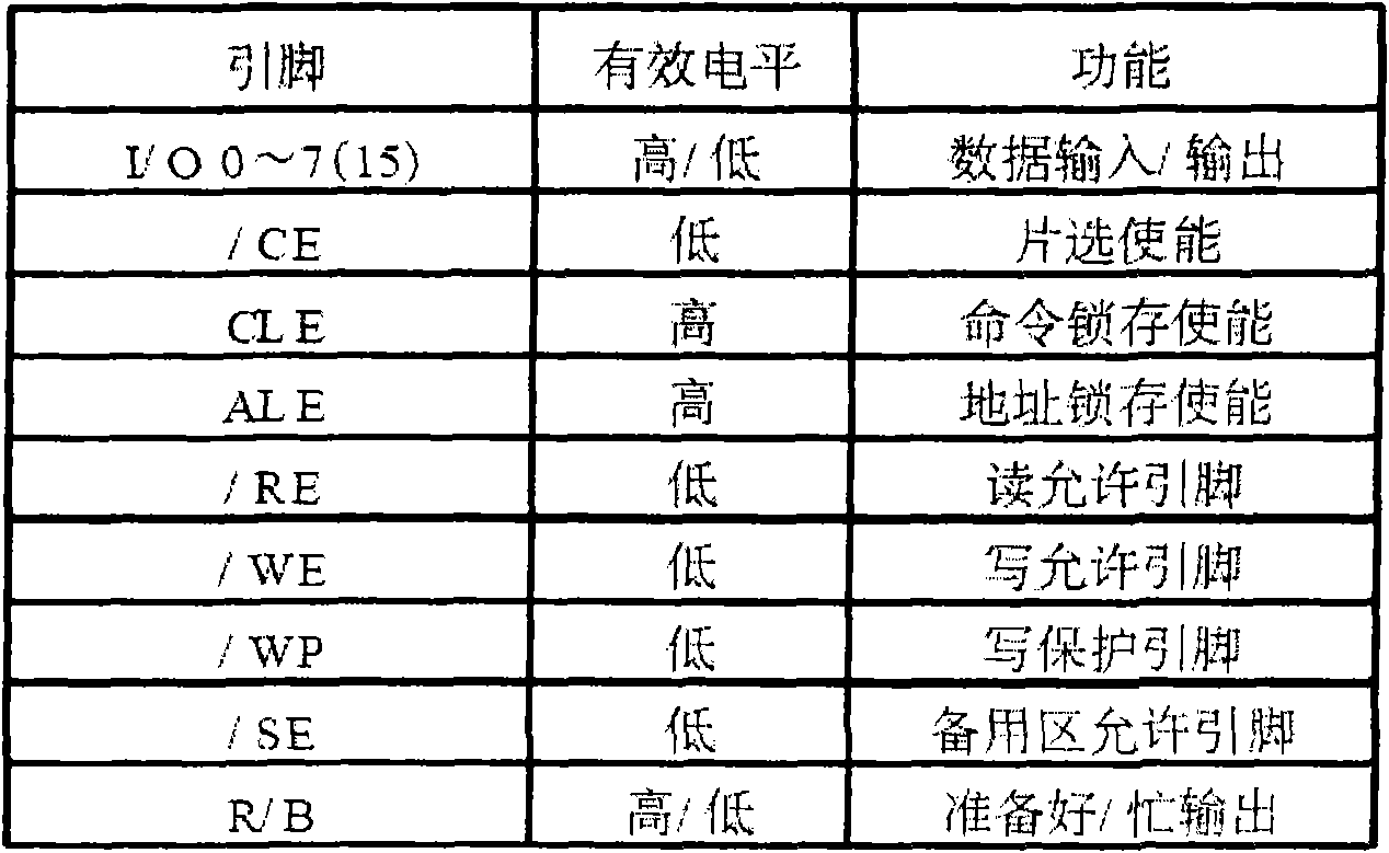
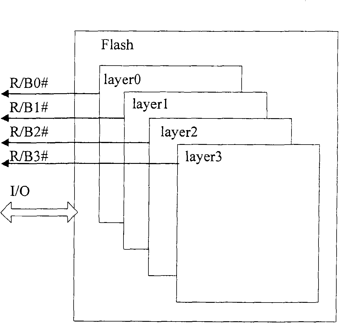
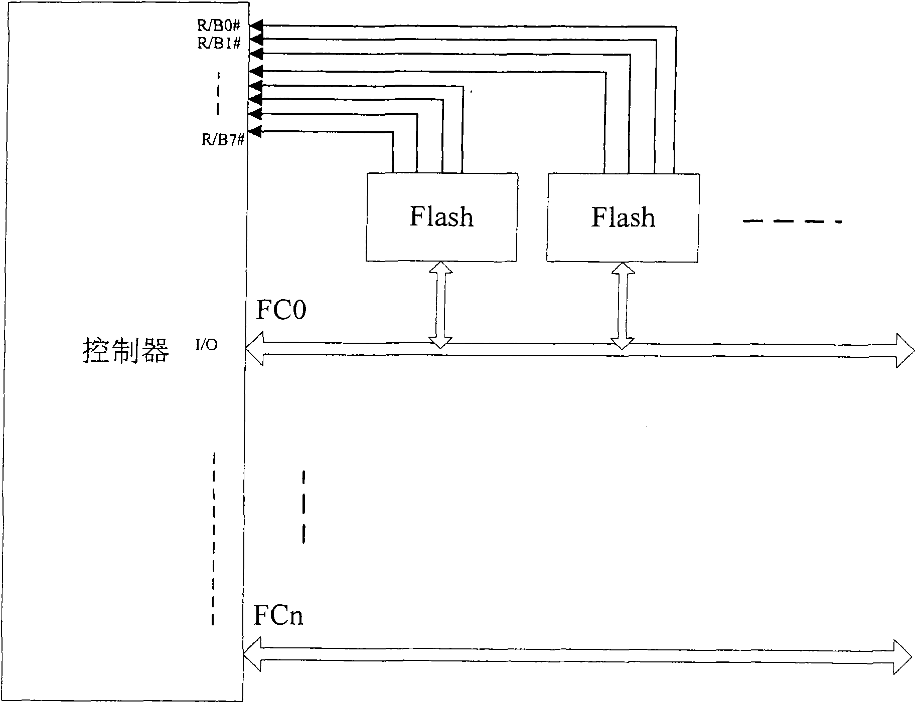
[0044] In one embodiment, the state of the layer in the Flash is idle / busy R / B# state; After the corresponding layer in the Flash has just received the state query command, by the input / output I / O pin of the Flash, The value of the I / O bit in the state register of the layer in the Flash is fed back to the Flash controller, and the value of the I / O bit corresponds to the state signal value of the layer in the Flash. In one embodiment, the status signal value is R / B# signal value, and the R / B# signal value of each layer in the Flash represents that the layer is in an idle / busy state.

[0045] Step 502, acquire the value of th...

Embodiment 2

[0059] Such as Figure 7 As shown, it is a schematic structural diagram of a Flash-based status query device according to an embodiment of the present invention, and the device 70 includes:

[0060] Information sending unit 701, is used for sending the status inquiry order of inquiry layer state to the layer in Flash, and this status inquiry order is used for inquiring about the state of described layer;

[0061] Information acquisition unit 702, for obtaining the value of the I / O bit in the status register of the layer in Flash, the value of this I / O bit corresponds to the status signal value of the layer in the Flash;

[0062] In one embodiment, the status signal value may be the R / B# signal value, and the R / B# signal value of each layer in the Flash represents that the layer is in an idle / busy state.

[0063] preferred, such as Figure 13 As shown, in one embodiment, the above information acquisition unit 702 may include:

[0064] The detection start module 7021 is used ...

Embodiment 3

[0087] The status query provided by the Flash chip detects the ready / busy status of the layer in the Flash through the status query command. There is an 8-bit status register inside the layer in Flash, which provides a software way to query the layer status in Flash.

[0088] Such as Figure 10 Shown is a schematic diagram of a state query sequence of an application example of the present invention, wherein:

[0089] t CLR Delay time from CLE to RE#, usually 10ns, t REA It is the data ready time, which can usually be 20ns. In addition, CE# is the chip select enable signal, CLE is the command latch signal, RE# is the read clock, and I / Ox is the data input / output.

[0090] The definition of each bit of the layer status register in Flash is as follows Figure 11 As shown, the 6th bit indicates the state of the layer of Flash. The controller sends the command 70h to the layer in the Flash, and the layer in the Flash sends out the value of the status register driven by the fal...


PUM


Abstract

The embodiment of the invention provides a method, a device and a system for inquiring the state based on Flash; the method comprises the steps of: sending a state inquiry command to the layer in Flash; obtaining the value of I/O bit which corresponds to the state information value of the layer in Flash in a state register of the layer in Flash; and determining the state of the layer in Flash according to the value of the I/O bit. The embodiment of the invention also provides a state sending method based on Flash; the method comprises the steps of: receiving a state inquiry command which is sent by a Flash controller for inquiring the layer state; and feeding back the value of the I/O bit, which corresponds to the state information value of the layer in Flash in the state register of the layer in Flash to the Flash controller. The embodiment of the invention achieves the technical effect of effectively easing the lacked pin resources of the Flash controller.

Description

technical field [0001] The invention relates to a Flash storage device, in particular to a Flash-based state query method, device and system. Background technique [0002] NAND Flash is a non-volatile random access storage medium. Its characteristic is that the data does not disappear after power failure, so it can be used as an external memory. NAND Flash is divided into two types: SLC and MLC. SLC stands for Single Level Cell and MLC stands for Multi Level Cell. The difference between them is mainly in their structure. In the SLC chip, each storage unit only stores 1Bit data, so the cost is high and the price is expensive, but it has relatively high efficiency, fast speed, high reliability, long life and power saving. MLC uses a large number of voltage levels to store 2Bit or more bits of data in each storage unit. The data density is relatively high, but its performance and life are much worse than that of SLC, but its biggest advantage is its cheap price. [0003] Mos...

Claims


Application Information

Patent Timeline
IPC IPC(8): G06F13/16
Inventor 周建华黎小红
Owner HUAWEI TECH CO LTD
Why Eureka
Try Eureka