Magnetic recognition system
A magnetic and labeling technology, which is applied in the direction of material inspection products, measuring devices, instruments, etc., can solve the problems of deterioration, protein orientation is not optimal, etc.
- Summary
- Abstract
- Description
- Claims
- Application Information
AI Technical Summary
Problems solved by technology
Method used
Image
Examples
Embodiment 1
[0156] Example 1 - Design and manufacture of fusion proteins
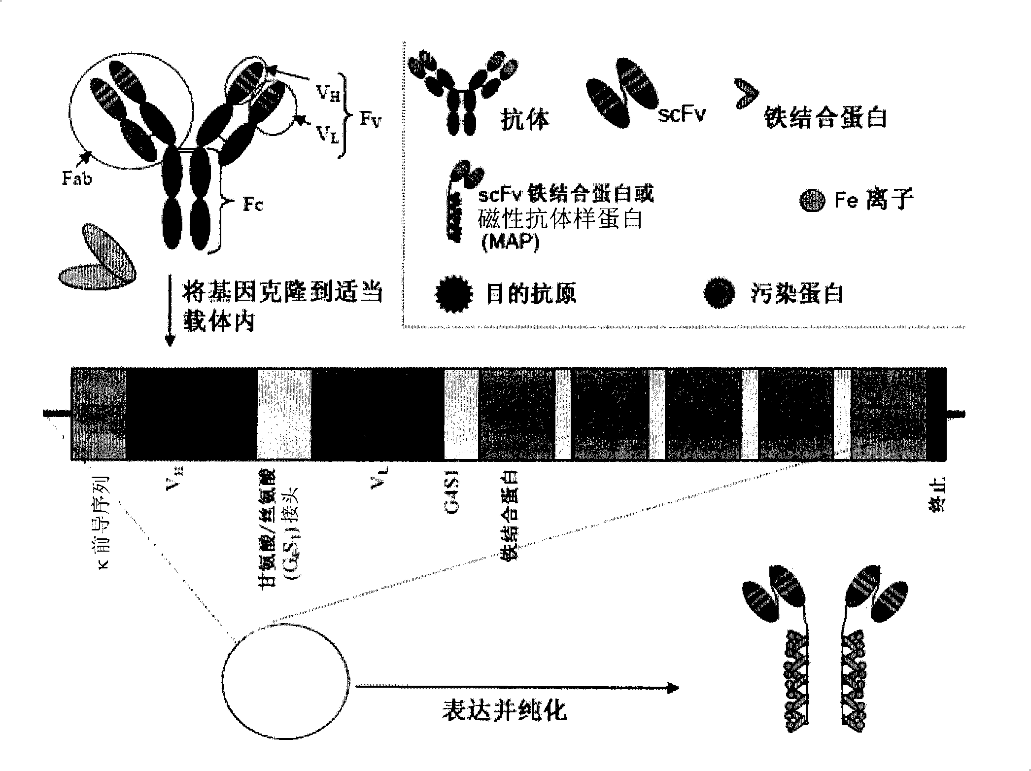
[0157] To illustrate the present invention, fusion proteins were designed using commercially available murine anti-fibronectin antibodies. Fusion proteins of anti-fibronectin scFvs genetically linked to MT2 or ferritin via a flexible short linker were prepared. This example details the construction, characterization and isolation of the fusion protein.
[0158] The design of the anti-fibronectin ferritin or MT2 fusion protein was based on combining V from a mouse anti-fibronectin antibody. H and V L The gene is cloned into the vector. Both genes are linked by flexible short linkers consisting of small uncharged amino acids. Immediately after V L At the 3' end of the gene, another flexible short linker is attached to the ferritin gene or the MT2 gene. Both fusion proteins have hexahistidine regions used for purification on nickel columns. Fusion protein translation is terminated at a stop codon inserted at th...
Embodiment 2
[0199] Example 2 - SPR Analysis
[0200] Anti-fibronectin ferritin and MT2 fusion protein inclusion body preparations were used in surface plasmon resonance (SPR) analysis using a SensiQ instrument (ICX Nomadics).
[0201] For these experiments, fibronectin peptides were coupled to the carboxyl chip surface. The fusion protein preparation was then flowed through the chip and binding (K a ) and dissociation (K d )dynamics.
[0202] Fusion protein analysis samples
[0203] Six samples of each fusion protein were prepared at various concentrations ranging from 0.0013 μM to 0.133 μM in running buffer, as shown in Tables 2 and 3 below.
[0204] Table 2 - Metallothionein Fusion Protein 75kDa:
[0205] 400 μL of 10 μg / mL (0.133 μM) from 40 μL of 100 μg / mL 75kDa / 360 μL running buffer, then
[0206] μM FP
μg / mL FP
10μg / mL FP (μL)
Running buffer (μL)
0.0013
0.1
20(of 1μg / mL)
180
0.0065
0.5
10
190
0.013
...
Embodiment 3
[0221] Example 3 - Magnetoferritin
[0222] Ferritin usually contains hydrated iron (III) oxide. To generate paramagnetic ferritin, magnetite (Fe 3 O 4 ) to replace these ions. The method used for this experiment involved adding iron ions to apoferritin and oxidizing these ions under controlled conditions.
[0223] Material
[0224] ●Reverse osmosis water (RO water)
[0225] 50mM N-(1,1-dimethyl-2-hydroxyethyl)-3-amino-2-hydroxypropanesulfonic acid (AMPSO) buffer (pH 8.6) (Sigma A6659)
[0226] ●0.1M sodium acetate buffer (pH4.5)
[0227] Phosphate-buffered saline (PBS), 10 mM phosphate, 140 mM NaCl (pH 7.4)
[0228] ●Trimethylamine-N-oxide (TMA) (Sigma 317594)
[0229] 0.1M ammonium ferrous(II) sulfate
[0230] Horse spleen apoferritin (Sigma A3641)
[0231] method
[0232] Heat trimethylamine-N-oxide (TMA) to 80 °C (30 min) in an oven to remove Me 3 N, then cooled to room temperature. 114 mg of TMA was added to 15 mL of RO water to produce a 0.07M solution. Iro...
PUM
| Property | Measurement | Unit |
|---|---|---|
| Diameter | aaaaa | aaaaa |
| Diameter | aaaaa | aaaaa |
| Molecular weight | aaaaa | aaaaa |
Abstract
Description
Claims
Application Information
 - R&D
- Intellectual Property
- Life Sciences
- Materials
- Tech Scout
- Unparalleled Data Quality
- Higher Quality Content
- 60% Fewer Hallucinations
Browse by: Latest US Patents, China's latest patents, Technical Efficacy Thesaurus, Application Domain, Technology Topic, Popular Technical Reports.
© 2025 PatSnap. All rights reserved.Legal|Privacy policy|Modern Slavery Act Transparency Statement|Sitemap|About US| Contact US: help@patsnap.com


