Multi-stage rotor pump and manufacturing process thereof

A manufacturing method and rotor pump technology, applied in the directions of rotary piston pumps, pumps, rotary piston machines, etc., can solve the problems of complicated manufacturing process and increased cost, and achieve the effects of easy parts manufacturing, shortening manufacturing process and cost reduction.

Inactive Publication Date: 2009-09-30
ANEST IWATA CORP
View PDF1 Cites 7 Cited by
  • Summary
  • Abstract
  • Description
  • Claims
  • Application Information

AI Technical Summary

Problems solved by technology

Therefore, the manufacturing process becomes complicated and the cost increases

Method used


Image

  • Multi-stage rotor pump and manufacturing process thereof
  • Multi-stage rotor pump and manufacturing process thereof
  • Multi-stage rotor pump and manufacturing process thereof

Examples


Embodiment 1

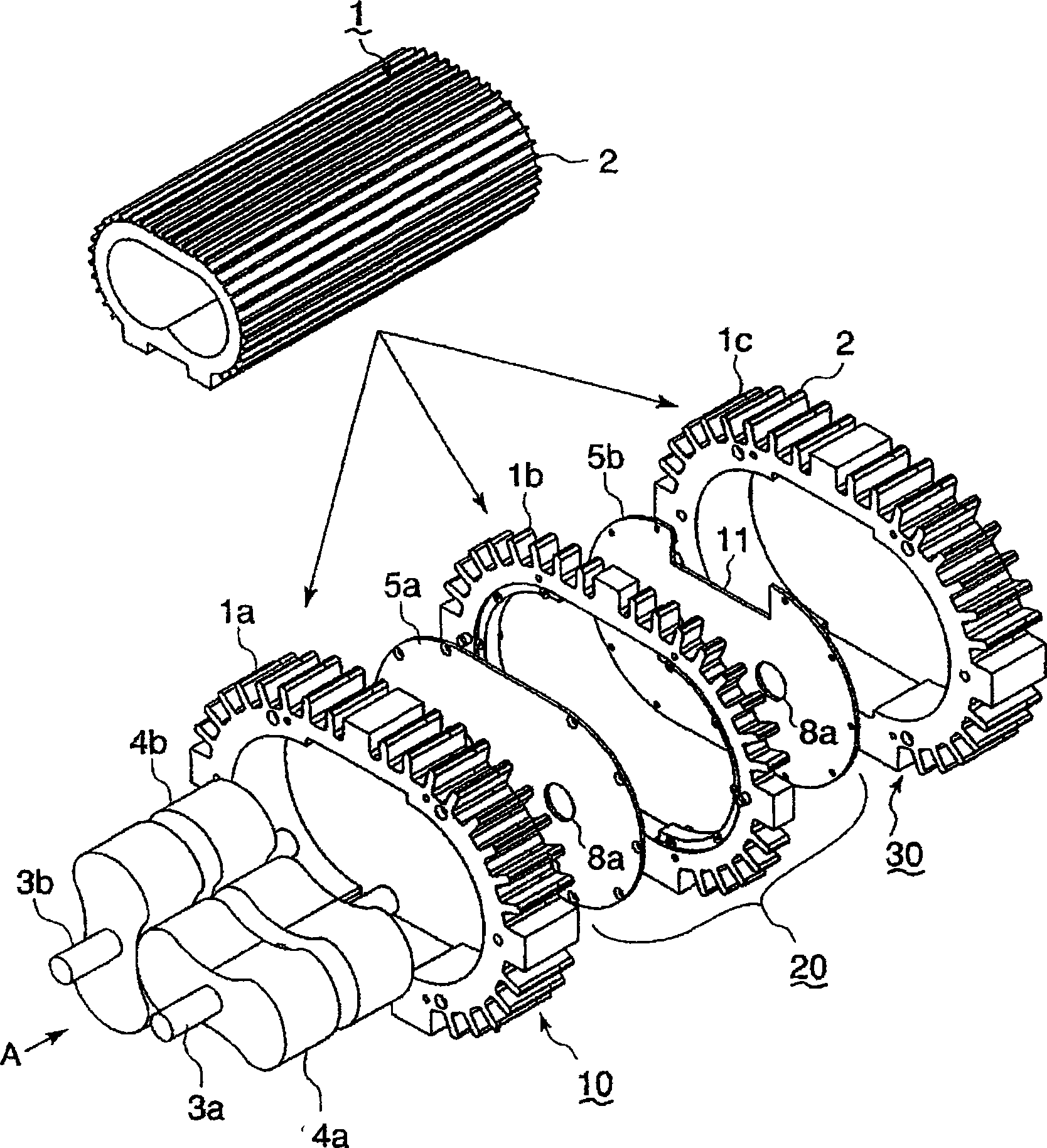
[0046] according to Figure 1 to Figure 4 A first embodiment in which the present invention is applied to a Roots pump equipped with a cocoon-type (cocoon-type) rotor will be described. figure 1 It is a perspective view showing the process of manufacturing a multi-stage vacuum pump from an aluminum cylinder 1 formed by extrusion processing, figure 2 It is a three-dimensional view showing a part of it selected.

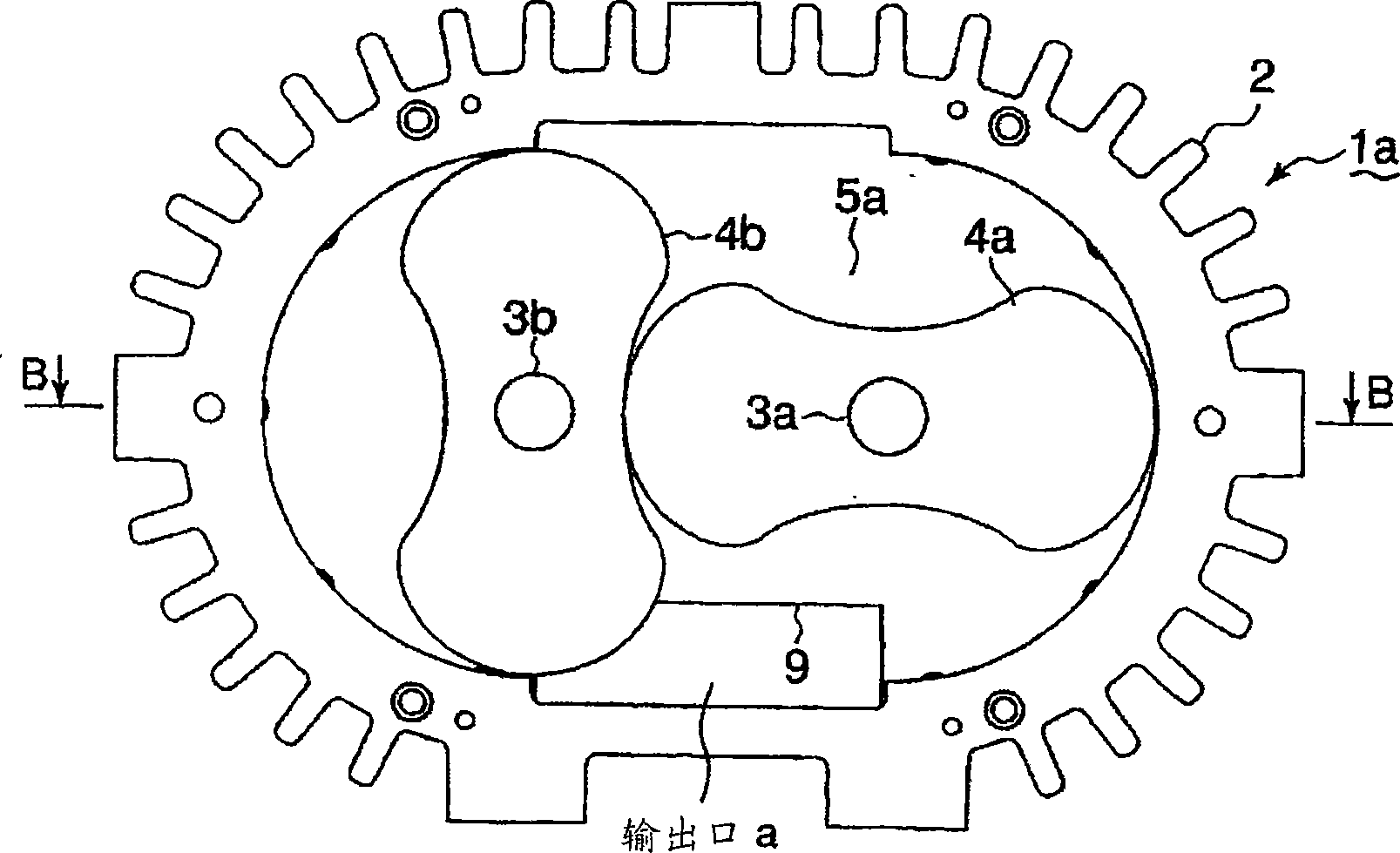
[0047] figure 1 and figure 2 Among them, the cylindrical body 1 is a structure in which the cross section is formed into the same shape and the same size by using a die for drawing or extrusion molding. At this time, when the cylindrical body 1 is made of aluminum, it is formed by extrusion, and when the cylindrical body 1 is made of a copper alloy such as brass, it is formed by drawing. When the cylindrical body 1 is formed, the cooling fins 2 extending in the long-axis direction are simultaneously formed on the outer peripheral surface of the cylindrical body 1...

Embodiment 2

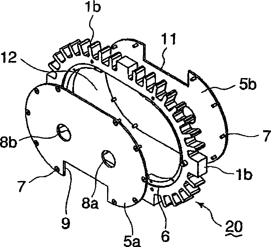
[0064] The following is based on Figure 5 A second embodiment of the present invention will be described. This example is an example showing another structure of the partition wall, and the other structures are the same as those of the above-mentioned first example. Figure 5 It is a perspective view which shows the structure of the partition wall of this Example. Figure 5 Among them, the partition wall 40 is constituted by a plate-shaped body. The partition wall 40 is provided with two rotor shaft passing holes 41 a and 41 b through which the rotor shafts 3 a and 3 b pass. Figure 5 The illustration of the cylindrical body 1b as an outer contour surrounding the plate-shaped body is omitted.

[0065] An opening 42 is opened below the rotor shaft passing holes 41a, 41b, and the opening 42 communicates with the discharge port a of the rotor chamber formed by the first-stage rotor housing 10, and an opening 43 is opened above the rotor shaft passing holes. The opening 43 co...

Embodiment 3

[0068] The following is based on Figure 6 A third embodiment of the present invention will be described. This embodiment also represents other structures of the partition wall, Figure 6 is a cross-sectional view showing the partition wall of this embodiment. Figure 6 Among them, the partition wall 50 of this embodiment has a structure in which a plurality of plates 51 are laminated inside a cylindrical body 1b as an outer contour body. Rotor shaft passing holes 52 through which the rotor shafts 3a and 3b pass are opened on each laminated plate 51, and holes or recesses are opened to form a fluid flow path 50, which will be formed by the first-stage rotor casing 10. The discharge port a of the upstream rotor chamber constituted communicates with the suction port of the downstream rotor chamber constituted by the second-stage rotor casing 30 .

[0069] For example, a recess 53 communicating with the discharge port a is provided on the plate 51a facing the cylindrical body ...


PUM


Abstract

The invention relates to a multi-stage rotor pump and the manufacturing process thereof. The multi-stage rotor pump is provided with a rotor shaft in the housing equipped with a plurality of rotor chamber, a multi-stage rotor is fixedly disposed on the rotor shaft. In order to produce the multi-stage rotor pump simply and with low cost, a hollow cylinder body with cross sections in the same shape is formed. When the cylinder is formed, radiating ribs extending along the longitudinal axis direction are formed on the outer circumferential surface of the cylinder simultaneously, the cross section interposing with the longitudinal axis cuts the cylinder which is used as a plurality of rotor housing. Rotor shafts are configured inside the plurality of rotor housing, and a multi-stage rotor is fixedly disposed on the rotor shafts inside each rotor housing. Because the separation board opened with rotor shaft through holes covers the inlet side and the outlet side of the rotor housing, a fluid path communicating the outlets of the front and the rear rotor housing with the inlet is formed on the separation wall.

Description

technical field [0001] The invention relates to a multi-stage rotor pump and a manufacturing method thereof, which can simultaneously form a casing and a partition wall of a multi-stage rotor pump assembled from multi-stage rotors by one mould, and the manufacturing process is simplified. Background technique [0002] At present, housings containing rotating bodies such as vacuum pumps are generally manufactured by casting or forging. Therefore, in the case of a multistage rotor pump in which rotors are assembled in multiple stages, even if the cross-sectional shape is the same but only the depth dimension is different, different molds must be prepared and manufactured. [0003] Patent Document 1 (Japanese Unexamined Patent Publication No. 5-18379) discloses such a multi-stage Roots-type vacuum pump: it is composed of a rotor housing divided into two parts parallel to the rotor axis, the shaft is made of iron material, and the shaft is made of aluminum alloy. Castings etc. ...

Claims


Application Information

Patent Timeline
Patent Type & Authority Applications(China)
IPC IPC(8): F04C25/02F04C18/14
Inventor 谷川志郎
Owner ANEST IWATA CORP
Why Eureka
Try Eureka