
On-line monitoring oil-gas separation device for transformer

A separation device, oil and gas separation chamber technology, applied in transformer/inductor cooling, separation method, liquid degassing, etc., can solve the problems of difficult separation, deterioration, pollution, etc., achieve high degassing efficiency, convenient installation, and overcome pollution. Effect

Inactive Publication Date: 2009-09-30
SHANGHAI JIAO TONG UNIV
View PDF0 Cites 36 Cited by
  • Summary
  • Abstract
  • Description
  • Claims
  • Application Information

AI Technical Summary

Problems solved by technology

However, it takes more than ten or even dozens of hours to separate, and the separation is not very complete
In addition, after the polymer breathable membrane is soaked in transformer oil for a long time, it will cause the deformation and deterioration of the membrane, which requires the staff to replace the polymer membrane after a period of time
[0005] (2) The oil-gas separation device based on the principle of vacuuming uses a small motor to drive the bellows to compress repeatedly, and vacuumizes repeatedly to extract the dissolved gas in the oil, and the waste oil is still returned to the transformer. Although each test takes 40 minutes, the test The period can be tuned within 1-99h or 1-99 years, but because the residual oil accumulated in the gap of the bellows is difficult to completely discharge, it will contaminate the oil sample for the next test, and the dissolved gas components in the oil cannot be truly measured Content and its change trend, while the separation is not thorough enough, some gases are difficult to separate
However, due to the need to introduce air during the oil-gas separation process, various gases in the air will inevitably pollute the detected gas

Method used

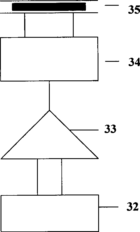
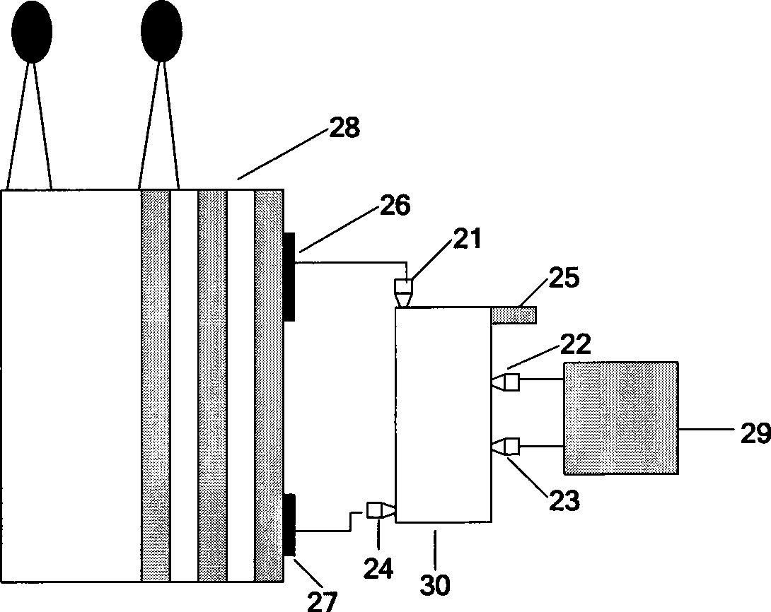

Image

  • On-line monitoring oil-gas separation device for transformer
  • On-line monitoring oil-gas separation device for transformer
  • On-line monitoring oil-gas separation device for transformer

Examples


Embodiment Construction

[0019] The embodiments of the present invention are described in detail below in conjunction with the accompanying drawings: this embodiment is implemented on the premise of the technical solution of the present invention, and detailed implementation methods and specific operating procedures are provided, but the protection scope of the present invention is not limited to the following the described embodiment.

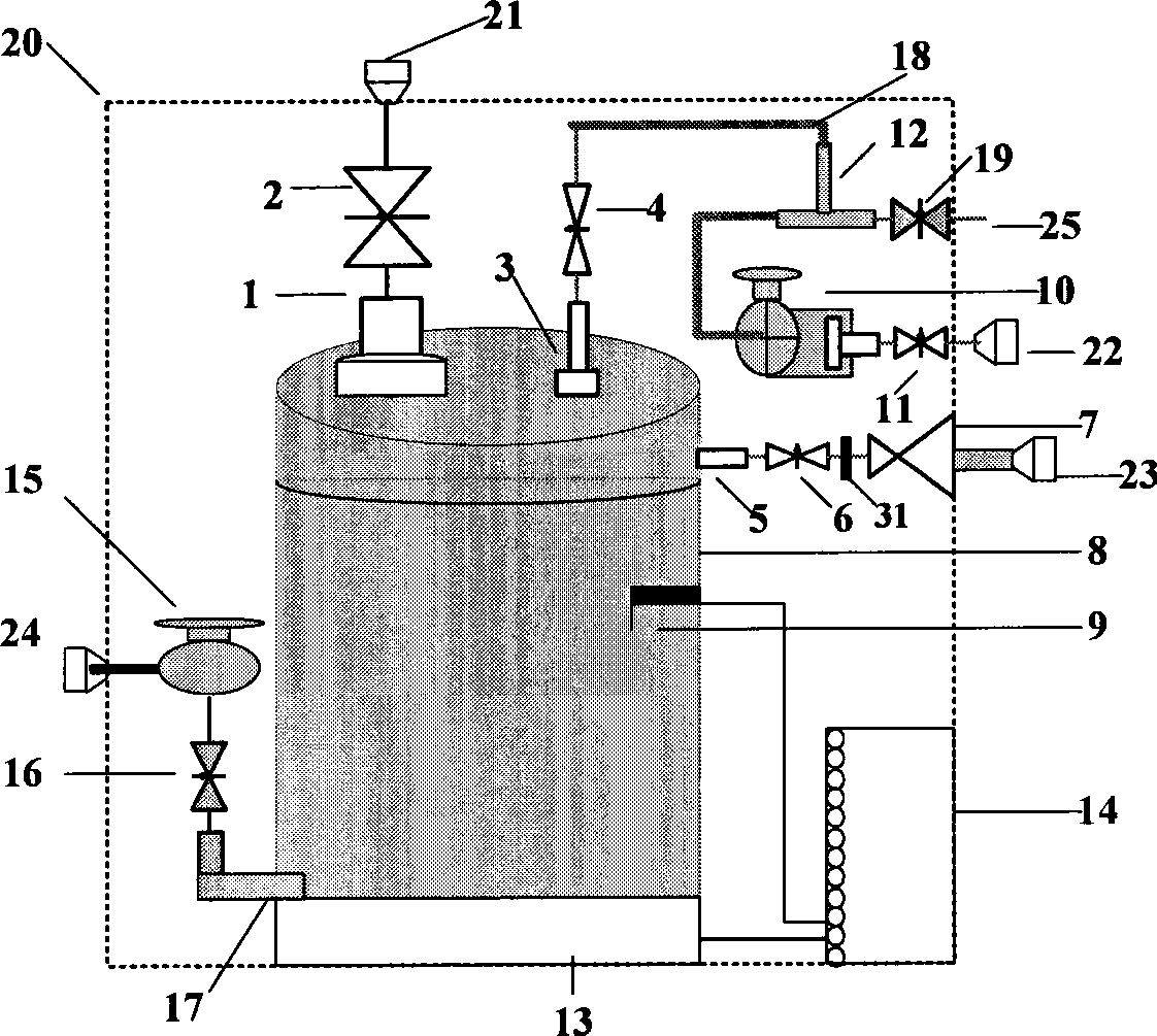
[0020] Such as figure 1 As shown, this embodiment includes: an oil inlet 1, a solenoid valve 2, an air inlet 3, a solenoid valve 4, an air outlet 5, a solenoid valve 6, a flow limiting valve 7, an oil-gas separation chamber 8, a liquid level detector 9, Vacuum pump 10, electromagnetic valve 11, T-shaped pipe 12, ultrasonic oscillator 13, PLC control module 14, oil return pump 15, electromagnetic valve 16, oil return port 17, polytetrafluoroethylene tube 18, electromagnetic valve 19, shielding box 20, Oil inlet valve external terminal 21, vacuum pump external terminal...


PUM


Abstract

The invention relates to an on-line monitoring oil-gas separation device for a transformer, and belongs to the technical field of power engineering. The device comprises an oil-gas separation chamber, a vacuum pump, an ultrasonic vibrator, a scavenge oil pump, a PLC control module, an electromagnetic valve, a liquid level detector, an oil-gas filter, a throttle valve and a connecting pipe. All electric parts are controlled by the PLC module to cooperate with each other to work in real time. The device utilizes a method of combining the vacuum pumping and the sonic oscillation principle for the oil-gas separation, so that the degassing efficiency is higher and the degassing process is faster; and moreover, the device also has the advantages of high automaticity, small volume and convenient arrangement, and is quite suitable for detecting faults based on dissolved gas in the oil of oil immersed type equipment such as a transformer and the like.

Description

technical field [0001] The invention relates to an oil-gas separation device in the technical field of electric power engineering, in particular to a transformer online monitoring oil-gas separation device based on the principle of ultrasonic oscillation. Background technique [0002] With the rapid development of power grid construction, the society has put forward higher requirements for the safety and stability of the power grid. The failure of electrical equipment, especially the failure of power transformers, has always been the main factor that endangers the stable and safe operation of the power grid. Therefore, real-time online monitoring of the operating status of power transformers is particularly important, which is directly related to the stable and reliable operation of the power grid. Rapidly separate out in real time. [0003] After searching the literature of the prior art, it was found that the book "On-line Monitoring and Fault Diagnosis of Gas in Oil of ...

Claims


Application Information

Patent Timeline
IPC IPC(8): H01F27/14B01D19/00
Inventor 贺绍鹏王俏华尹毅郑煜
Owner SHANGHAI JIAO TONG UNIV
Learn More