

Plasma processing apparatus
A plasma and processing device technology, applied in the field of plasma processing devices, can solve problems such as abnormal discharge, deterioration of uniformity, and damage to components or substrate S, and achieve the effects of suppressing arc light, suppressing abnormal discharge, and suppressing damage and loss
Active Publication Date: 2009-10-07
TOKYO ELECTRON LTD
View PDF1 Cites 10 Cited by
- Summary
- Abstract
- Description
- Claims
- Application Information
AI Technical Summary
Problems solved by technology
[0009] In addition, depending on the processing conditions such as gas flow rate and pressure, various pressure atmospheres are formed near the exhaust port of the exhaust passage 16 for the inflow gas in the processing container 10. Generally, the minimum voltage required to generate plasma between the electrodes is The pressure function of the space formed between the electrodes, therefore, combined with the above-mentioned main reasons, the lower electrode 11, which is the cathode electrode, and the mesh member 17 are prone to glow discharge.
[0010] As described above, if unnecessary capacitive coupling is formed between the lower electrode 11 and the mesh member 17 to locally generate a strong glow discharge, the space between the lower electrode 11 and the upper electrode 12, which is the original plasma generation space, will The plasma may become unstable. For example, it may induce arc-shaped abnormal discharge, that is, arc light, on the surface of the components or the substrate S in the processing container 10, so that the above-mentioned components or the substrate S are damaged or lost. In addition, due to the deflected plasma body, which may lead to poor in-plane uniformity of the processed substrate S
Method used
View moreImage
Smart ImageViewing Examples

Examples
Embodiment 1
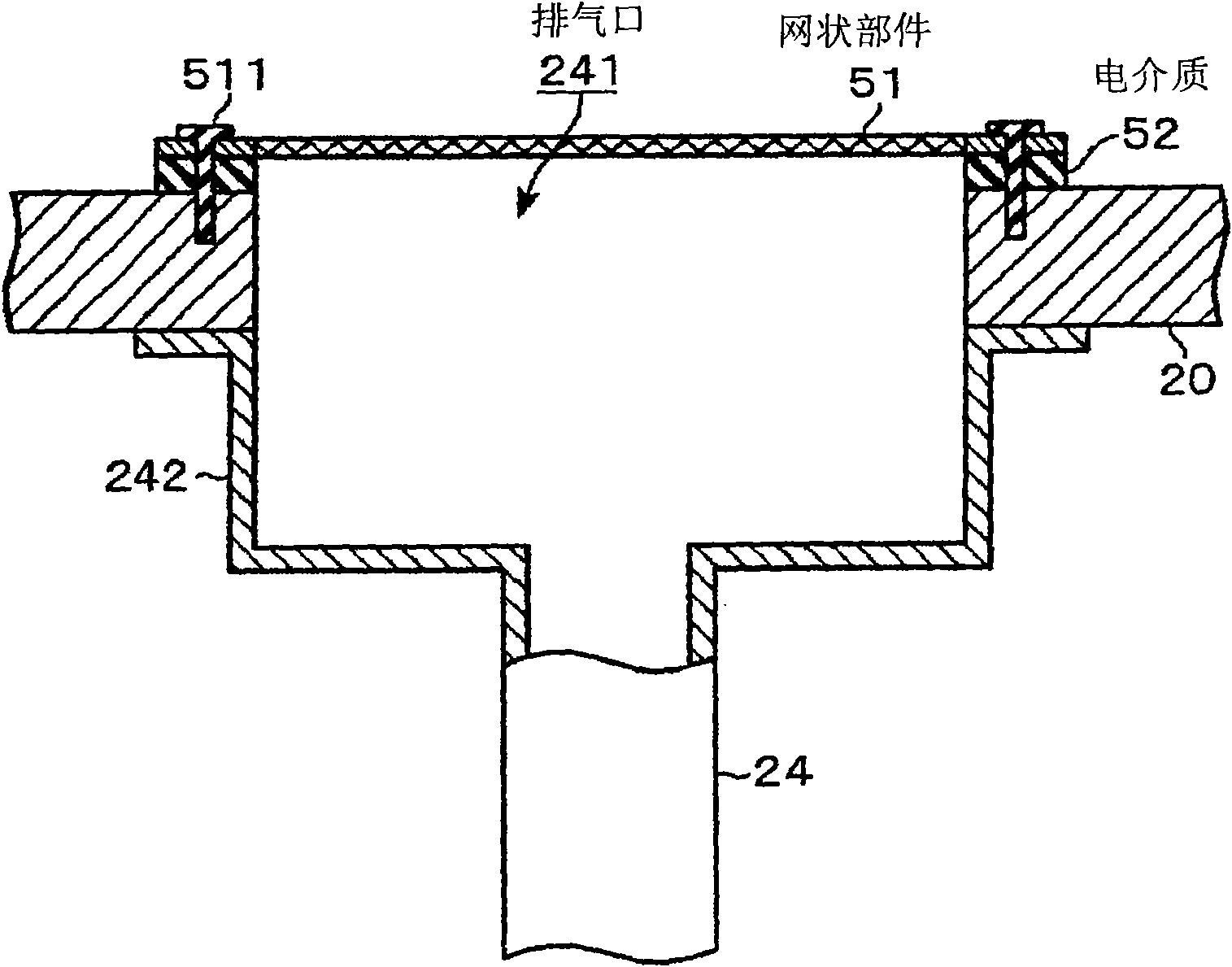
[0092] A dielectric 52 made of alumina is provided between the mesh member 51 b and the bottom wall surface of the processing container 20 .
Embodiment 2
[0101] A dielectric 52 is provided between the mesh member 51 b and the processing container 20 .
Login to View More PUM
| Property | Measurement | Unit |
|---|---|---|
| Area | aaaaa | aaaaa |
Abstract
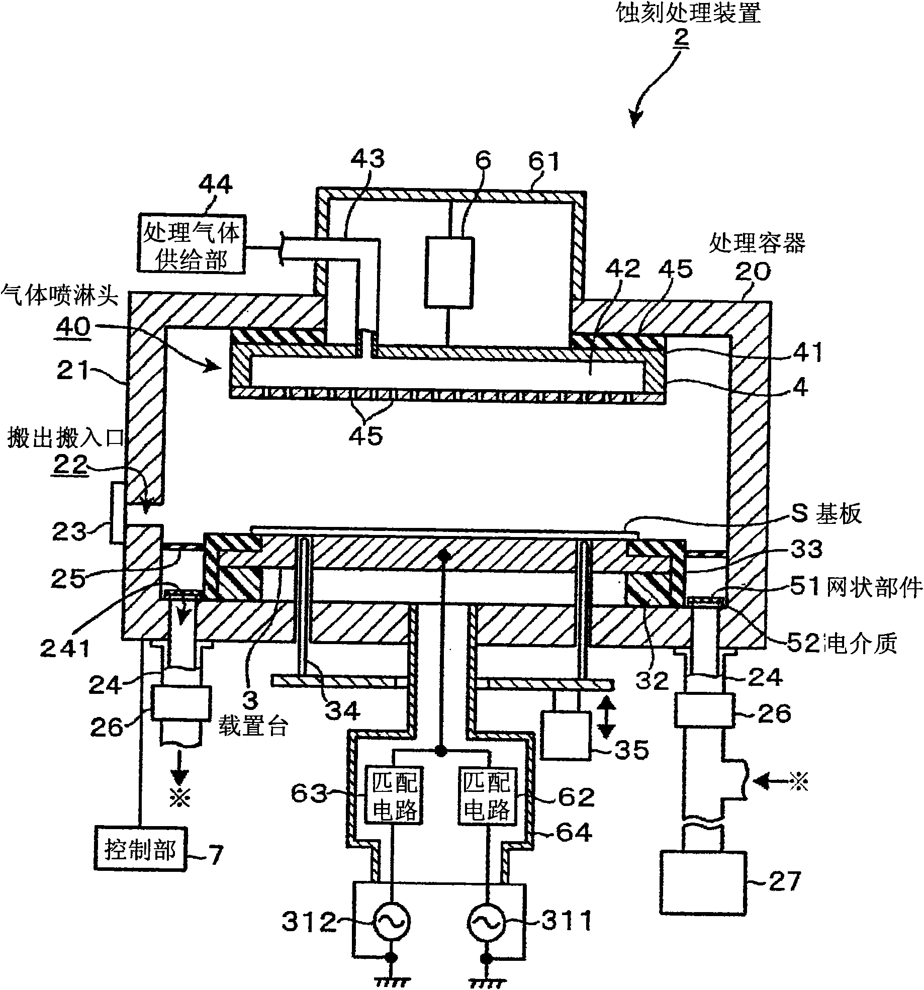
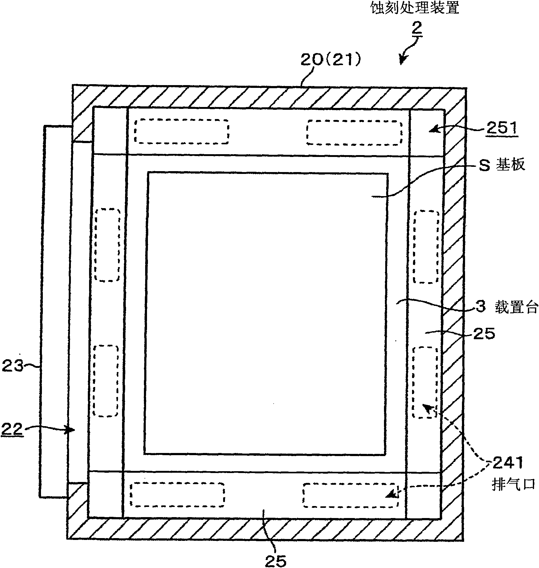
The present invention provides a plasma processing apparatus, capable of restraining an abnormal discharge from generating between a cathode electrode and a netted member for shrouding an exhaust outlet in a parallel flat-plate type plasma processing apparatus. The plasma processing apparatus (2) applies a high frequency electric force between an anode electrode (gas spray head (40) ) and a cathode electrode (carrying bench (3)) facing with each other in a processing container (20) to implement a plasma treatment to the processing gas and implement a plasma treatment to a processed object (S), wherein a conductive member (netted member 51) having an opening is arranged around the cathode electrode to shroud the exhaust outlet for discharging the processing gas, and an electrolyte (52) is arranged between the conductive member and a conductive wall of the processing container (20).
Description
[0001] technology area [0002] The present invention relates to a plasma processing apparatus that converts a processing gas into plasma by high-frequency power, and performs processing such as etching on an object to be processed by the plasma. Background technique [0003] In the manufacturing process of flat panels such as semiconductor equipment and liquid crystal display devices, in order to perform processing such as etching or film formation on semiconductor wafers or substrates to be processed called glass substrates, plasma etching equipment or plasma CVD is used. Plasma processing equipment such as membrane equipment. [0004] Figure 8 The shown plasma processing apparatus is a configuration example of a plasma etching apparatus for etching a thin film formed on a glass substrate for FPD (Flat Panel Display), for example. This plasma etching apparatus is configured as a parallel plate type plasma processing apparatus in which an upper electrode 12 is provided in a...
Claims
Login to View More Application Information
Patent Timeline
 IPC IPC(8): H01L21/00H01L21/3065H01L21/311H01L21/20H05H1/24
CPCH01J37/3244H01J37/32633H01J37/32807H01L21/3065H01L21/67069H05H1/46
Inventor佐藤亮齐藤均
OwnerTOKYO ELECTRON LTD