Polarizing beam-splitting birefringence space light bridge

A polarization beam splitter and polarization beam splitting technology are applied in the field of coherent laser, which can solve the problems of difficult integration, complex process, not belonging to a space optical bridge, etc., and achieve the effect of compact structure and stable performance.

Inactive Publication Date: 2009-10-21
SHANGHAI INST OF OPTICS & FINE MECHANICS CHINESE ACAD OF SCI
View PDF0 Cites 14 Cited by
  • Summary
  • Abstract
  • Description
  • Claims
  • Application Information

AI Technical Summary

Problems solved by technology

In the optical fiber communication system, the optical bridge is implemented by using the integration of optical fiber and waveguide, but these optical bridges suitable for the optical fiber communication system cannot meet the needs of space laser communication, and do not belong to the space optical bridge, because in free space laser communication In the system, the received optical signal is not only used to detect communication information, but also to extract position information for optical precision tracking. For free space laser communication terminals, the optical bridge must be free in space.
In free-space optical bridging, prior art [1], [2] (see document 1: Walter R.leeb.Realization of90°and 180°Hybrids for Optical Frequencies[C]. , Band 37[1983], Heft5/6: 203-206. Literature 2: R.Garreis, C.Zeiss, "90°optical hybrid for coherent receivers," Proc.SPIE, Vol.1522, pp.210-219, 1991 .) Proposed a 2×2 spatial optical bridge scheme using a polarizing beam splitter combined with a 1/4 wave plate, and a non-polarizing beam splitter combined with a 1/4 wave plate to achieve 90-degree and 180-degree phase shifts. Literature [2] states On this basis, a 2×4 90-degree phase shift implementation scheme is proposed, but this scheme has the disadvantages that the en

Method used


Image

  • Polarizing beam-splitting birefringence space light bridge
  • Polarizing beam-splitting birefringence space light bridge
  • Polarizing beam-splitting birefringence space light bridge

Examples


Embodiment Construction

[0013] The present invention will be further described in detail below in conjunction with the accompanying drawings and examples, but the protection scope of the present invention should not be limited thereby.

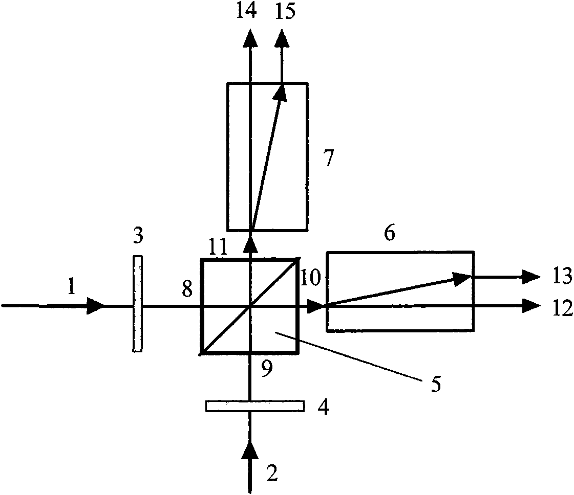
[0014] The structure of the polarized beam splitting birefringent spatial optical bridge of the present invention is as follows figure 1 As shown, it includes a first 1 / 8 wave plate 3 , a second 1 / 8 wave plate 4 , a polarizing beam splitter 5 , a first birefringent optical plate 6 and a second birefringent optical plate 7 . Wherein: the input light is the first light beam 1 and the second light beam 2 , and the output light is four light beams: the light beam 12 , the light beam 13 , the light beam 14 and the light beam 15 . The polarizing beam splitter 5 has a first incident surface 8 and a second incident surface 9 , a first exit surface 10 and a second exit surface 11 . The first 1 / 8 wave plate 3 is placed in front of the first incident surface 8 of the polarizat...


PUM


Abstract

The invention relates to a polarizing beam-splitting birefringence space light bridge, which is characterized by consisting of a first 1/8 wave plate, a second 1/8 wave plate, a polarizing beam splitter, a first birefringence optical flat and a second birefringence optical flat, wherein the first 1/8 wave plate, a first incident face of the polarizing beam splitter, a first emergent face and the first birefringence optical flat are arranged in turn along the advancing direction of a first light beam; the second 1/8 wave plate, a second incident face of the polarizing beam splitter, a second emergent face and the second birefringence optical flat are arranged in turn along the advancing direction of a second light beam; and the main cross section of the first birefringence optical flat is parallel to the main cross section of the first 1/8 wave plate, and the main cross section of the second birefringence optical flat is parallel to the main cross section of the second 1/8 wave plate. The polarizing beam-splitting birefringence space light bridge has the advantages of compact structure, stable performance, adjustable phase and the like, and is applicable to a coherent laser communication system with free space transmission.

Description

technical field [0001] The present invention relates to coherent laser communication, specifically a two-way input and four-way output phase-adjustable polarization beam-splitting birefringent spatial optical bridge. The polarization beam splitter spatially couples two input beams and splits them into four combined beams for output. The / 8 wave plate produces an adjustable phase shift, which is used in coherent laser communication for spatially recombining laser signal beams and local oscillator laser beams, and produces a 90-degree 2×4 spatial optical bridge that can be phase-controlled as required. Background technique [0002] Space-borne laser communication terminals with large capacity, high bit rate, small size, light weight and low power consumption have great application prospects in both military and civilian applications. Since the receiver sensitivity of coherent laser communication is more than an order of magnitude higher than that of incoherent optical communic...

Claims


Application Information

Patent Timeline
IPC IPC(8): G02B27/28G02B26/06G02B5/30H04B10/10H04B10/11
Inventor 万玲玉刘立人职亚楠周煜孙建锋许楠闫爱民
Owner SHANGHAI INST OF OPTICS & FINE MECHANICS CHINESE ACAD OF SCI
Why Eureka
Try Eureka