

Metal ceramic composite wear-resistant material and preparation method thereof
A metal-ceramic composite and wear-resistant material technology, applied in metal processing equipment, welding/cutting media/materials, welding equipment, etc., can solve the problems of wear-resistant ceramics easy to fall off, low bonding strength, and easy aging of adhesives. Achieve the effects of overcoming easy aging, high bonding strength, and expanding the scope of application
- Summary
- Abstract
- Description
- Claims
- Application Information
AI Technical Summary
Problems solved by technology
Method used
Image

Examples
Embodiment 1
[0044] The preparation method of metal-ceramic composite wear-resistant material is as follows:
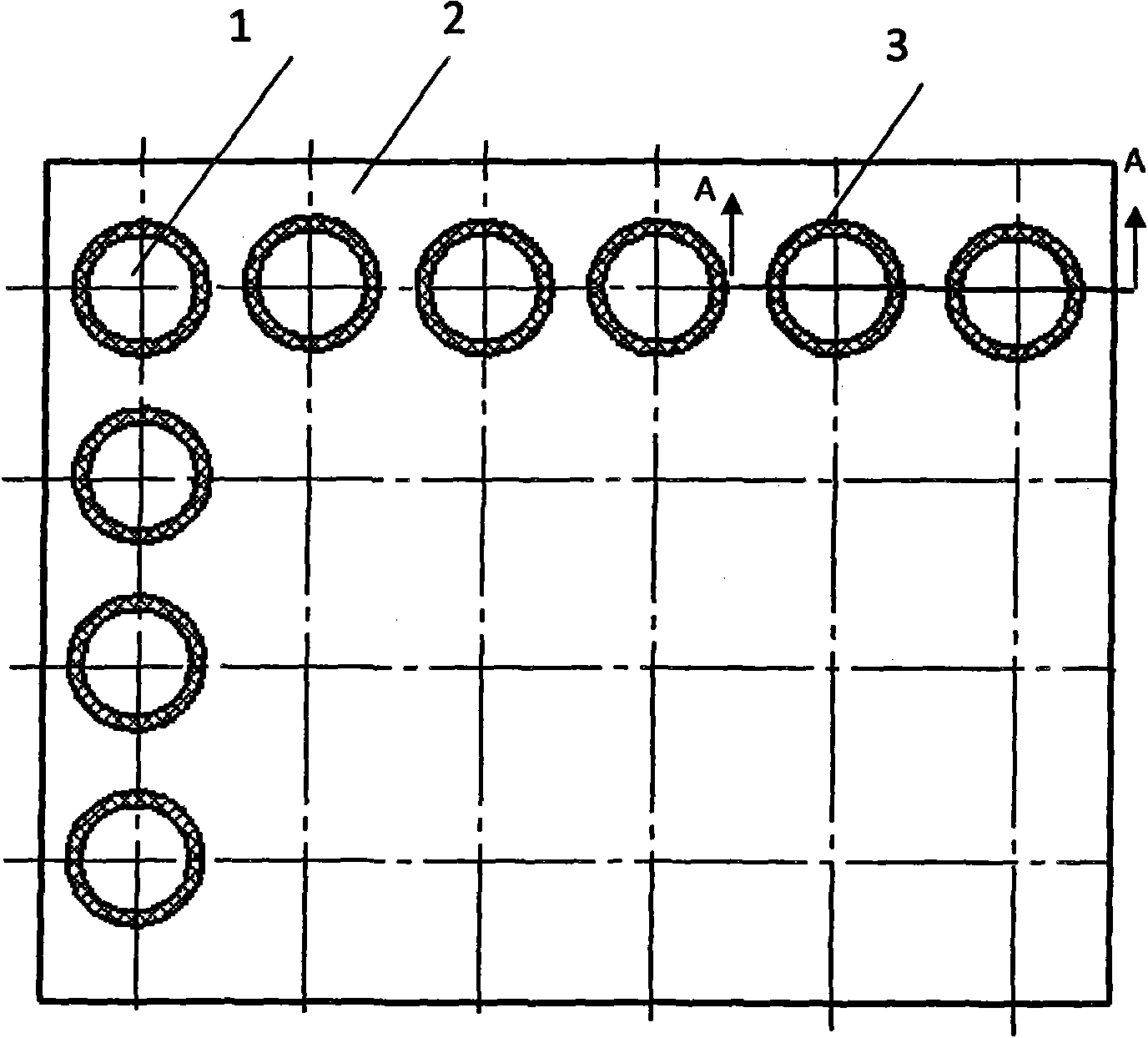
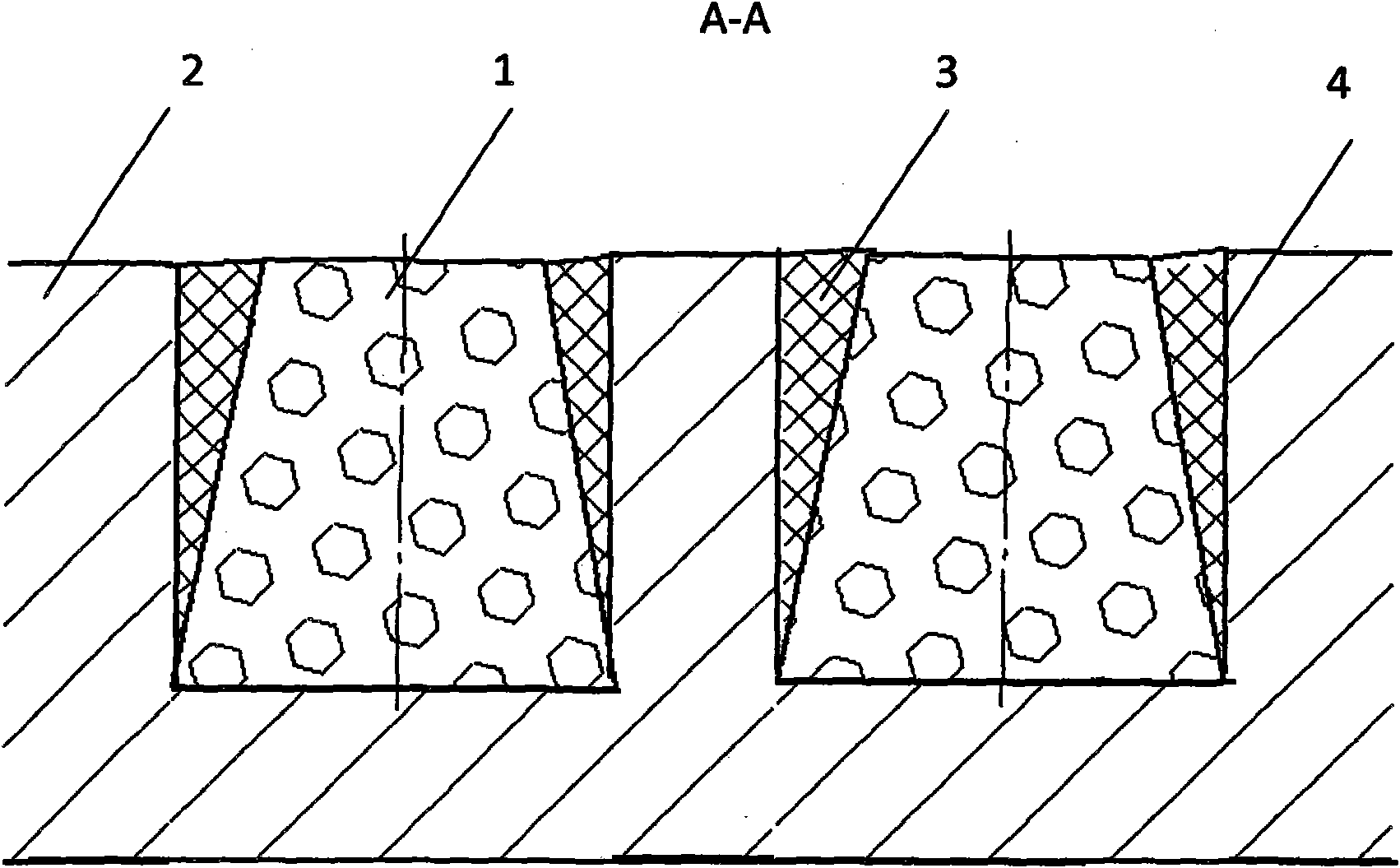
[0045] (1) Select substrate 2, and open blind hole 4 on substrate 2
[0046] The base plate 2 is low-carbon steel with a thickness of 20 mm, and its length and width are 305 mm and 200 mm, respectively. Open a number of blind holes 4 with a diameter of 10mm on the substrate 2. The depth of the blind holes 4 is 15mm. The thickness of the remaining metal in the blind holes 4 is 5mm. The blind holes 4 are evenly distributed on the substrate 2. The minimum spacing is 5mm, and the minimum distance from the blind hole 4 to the edge of the steel plate is 5mm.
[0047] (2) Adopt existing technology to prepare wear-resistant ceramic blocks, and match with the blind hole 4 opened in step (1)
[0048] The geometry of the wear-resistant ceramic block 1 is a perfect circular platform, the diameter of the lower bottom surface of the perfect circular platform is 10mm, the diameter of the upper...
Embodiment 2
[0055] (1) Select substrate 2, and open blind hole 4 on substrate 2
[0056] The base plate 2 is low-carbon steel with a thickness of 16 mm, and its length and width are 170 mm and 90 mm, respectively. Open a number of blind holes 4 with a diameter of 12mm on the substrate 2, the depth of the blind holes 4 is 10mm, the thickness of the remaining metal in the blind holes 4 is 6mm, the blind holes 4 are evenly distributed on the substrate 2, and the distance between the edges of adjacent blind holes 4 The minimum spacing is 4mm, and the minimum distance from the blind hole 4 to the edge of the steel plate is 5mm.
[0057] (2) Prepare the wear-resistant ceramic block 1 by using existing technology, and match with the blind hole opened in step (1)
[0058] The geometry of the wear-resistant ceramic block 1 is a cylinder with a diameter of 11 mm and a height of 10 mm. The size of the wear-resistant ceramic block 1 matches the size of the blind hole 4 on the substrate 2, and the m...
Embodiment 3
[0065] (1) Select substrate 2, and open blind hole 4 on substrate 2
[0066] The base plate 2 is low-carbon steel with a thickness of 18 mm, and its length and width are 305 mm and 200 mm, respectively. Open a number of blind holes 4 with a diameter of 10mm on the substrate 2, the depth of the blind holes 4 is 12mm, and the thickness of the remaining metal in the blind holes 4 is 6mm. The blind holes 4 are evenly distributed on the substrate 2. The minimum spacing is 5mm, and the minimum distance from the blind hole 4 to the edge of the steel plate is 5mm.
[0067] (2) Adopt existing technology to prepare wear-resistant ceramic block 1, and match with the blind hole 4 opened in step (1)
[0068] The geometry of the wear-resistant ceramic block 1 is a perfect circular platform, the diameter of the lower bottom surface of the perfect circular platform is 10mm, the diameter of the upper bottom surface is 6mm, and the height is 12mm. The size of the wear-resistant ceramic block ...
PUM
| Property | Measurement | Unit |
|---|---|---|
| Thickness | aaaaa | aaaaa |
| Area | aaaaa | aaaaa |
| Height | aaaaa | aaaaa |
Abstract
Description
Claims
Application Information