Method for measuring object deformation in real time

A real-time measurement and object technology, applied in measurement devices, instruments, optical devices, etc., can solve the problems of expensive equipment, insufficient sensitivity and accuracy, and large impact, and achieve the effect of improving the overall measurement accuracy and lighting quality.

Inactive Publication Date: 2009-10-28
XI AN JIAOTONG UNIV
View PDF0 Cites 102 Cited by
  • Summary
  • Abstract
  • Description
  • Claims
  • Application Information

AI Technical Summary

Problems solved by technology

The holographic interferometry has high detection sensitivity and precision. The disadvantage is that it has no penetrating ability to opaque objects. Generally, it can only be used for thin materials with small thickness. The equipment is relatively expensive, and it is affected by mechanical vibration, acoustic vibration ( Such as environmental noise) and ambient light, etc. have great interference, so it needs to be tested in a quiet and clean dark room
However, when the moiré method is used to measure small strains in the elastic range, the sensitivity and accuracy are not enough, and this method is greatly affected by external vibrations.
Since the electronic speckle interferometry technology is based on two-beam interference, it has certain requirements for the detection environment and the detection object, the experiment is difficult, and the equipment is expensive, which limits the general application of this technology.

Method used


Image

  • Method for measuring object deformation in real time
  • Method for measuring object deformation in real time
  • Method for measuring object deformation in real time

Examples


Embodiment Construction

[0040] The present invention will be further described in detail below in conjunction with the accompanying drawings and embodiments.

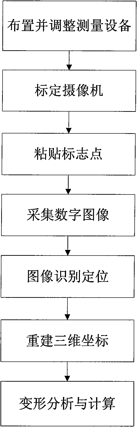
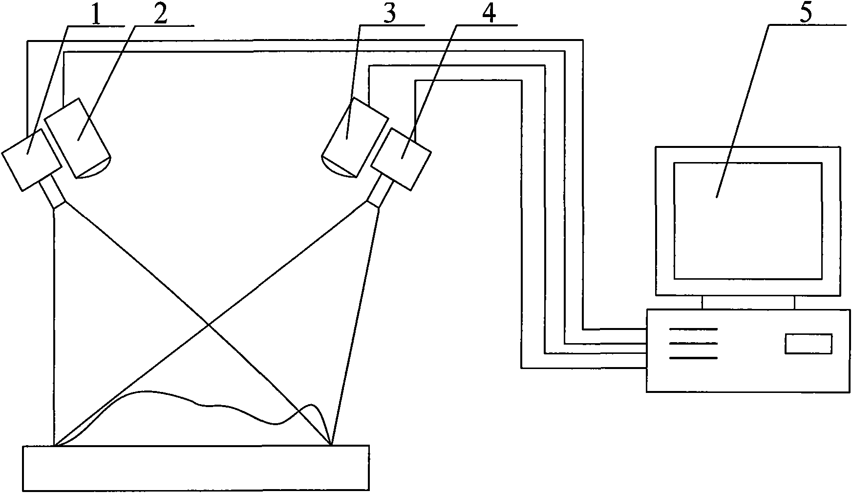
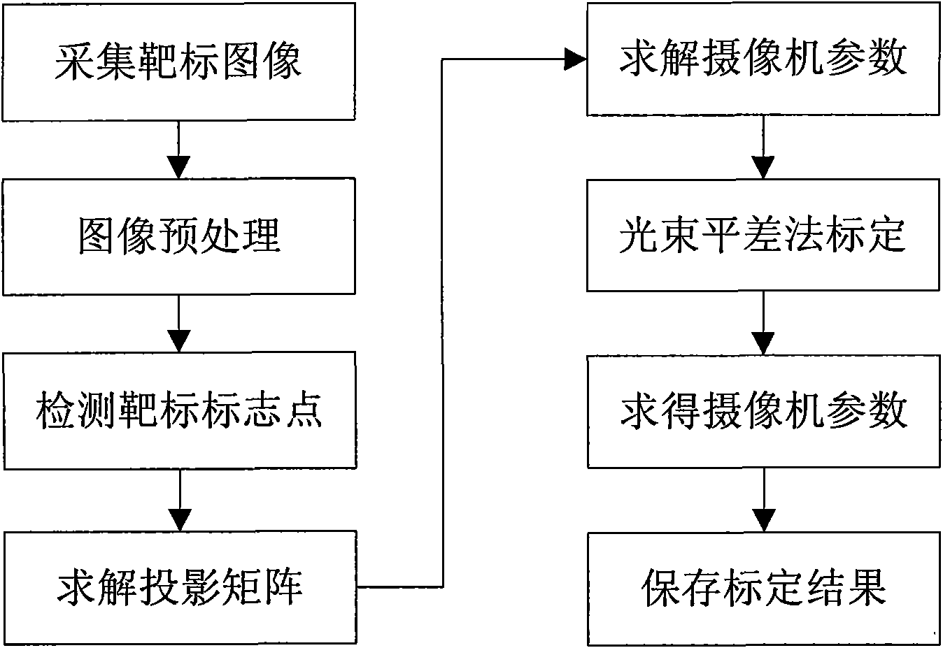
[0041] The present invention proposes a real-time measurement method for object deformation, such as figure 1 shown. measurement system such as figure 2 As shown, it is composed of CCD cameras 1, 4, LED lighting lamps 2, 3, computer 5 and so on. Computer 5 is a Pentium(R) 4CPU, 2.66GHz, with a 1394 image acquisition card, and supports dual monitor output. The software is independently developed based on Visual C++6.0 platform. The CCD adopts the A500 series camera from Basler in Germany. The camera adopts Camera Link output, external synchronization or internal autonomous operation, and the frame rate can reach 500fps when the resolution is 1280*1024, and the camera can be programmed and controlled.

[0042] figure 1 The overall steps of the inventive method shown are as follows:

[0043] (1) Arrange and adjust the measuring equipment: ...


PUM


Abstract

The invention discloses a method for measuring object deformation in real time, which comprises the following steps: arranging and adjusting measuring equipment, namely symmetrically arranging two cameras and corresponding LED illumination lamps above a measured object, and making optical axes of the two cameras intersected in a distance of 1 meter in front of the cameras; then calibrating the cameras, namely tightly sticking mark points to the surface of an object to be measured according to the size and shape of the measured object and the measurement requirement; next, placing the measured object stuck with the mark points under the two cameras in about 1 meter or moving the whole measuring equipment to make the measured object enter a measurement range and enable each camera to acquire the mark points on the surface of the measured object, starting the two cameras to shoot sequence images, and acquiring digital images; then identifying and positioning the images; reversely solving a projection matrix according to the calibration result of the cameras, and combining image coordinates of the solved mark points on the surface of the measured object on the images of the two cameras to reconstruct a three-dimensional coordinate of the mark points; and finally, carrying out deformation analysis and calculation for the mark points on the surface of the measured object.

Description

technical field [0001] The invention relates to a three-dimensional optical measurement method, in particular to a real-time measurement method suitable for object deformation. Background technique [0002] Deformation measurement is an important part of solid mechanics and material science research. Therefore, accurate, fast and efficient measurement of material deformation is an important research content of experimental mechanics. There are mainly two types of methods to dynamically measure the motion and deformation information of objects: contact and non-contact. [0003] Contact measurement methods mainly include photoelastic patch method and resistance strain gauge measurement method. Among them, the photoelastic patch method can be used to measure the dynamic stress, static stress, elastic stress and residual stress of structures or parts made of metal, concrete, wood, rock, rubber and other materials, but this method has very high requirements for the patch. High,...

Claims


Application Information

Patent Timeline
Patent Type & Authority Applications(China)
IPC IPC(8): G01B11/16
Inventor 梁晋肖振中胡浩唐正宗史宝全
Owner XI AN JIAOTONG UNIV
Why Eureka
Try Eureka