Eureka AIR delivers breakthrough ideas for toughest innovation challenges, trusted by R&D personnel around the world.

Method for monitoring steel bar corrosion state in concrete by stages and sensor

A steel bar corrosion and concrete technology, which is applied in the directions of transmittance measurement, phase influence characteristic measurement, optical test defect/defect, etc., can solve the problem that LPFG transmission resonance spectrum parameters cannot be obtained, the state of steel bar corrosion cannot be truly reflected, and the effective monitoring time of sensors is shortened and other problems, to achieve high resolution, overcome the influence of unstable light source, and prolong the effective working time

Inactive Publication Date: 2009-10-28
NANJING UNIV OF AERONAUTICS & ASTRONAUTICS
View PDF0 Cites 29 Cited by
  • Summary
  • Abstract
  • Description
  • Claims
  • Application Information

AI Technical Summary

Problems solved by technology

However, since the sensor can only monitor the radial expansion of the volume of the steel bar after corrosion (that is, the second stage), it cannot realize the monitoring of the volume expansion of the steel bar in the early stage of corrosion (that is, the first stage), so that the effective monitoring time of the sensor is greatly shortened
At the same time, due to the limitations of LPFG in monitoring the bending effect, that is, when the LPFG reaches a certain curvature, the transmittance in the LPFG transmission spectrum increases, such as Figure 9 As shown, the coupling phenomenon between the LPFG core guided mode and the cladding mode disappears, and the resonance peak disappears. At this time, the LPFG transmission resonance spectrum parameters cannot be obtained, that is, the sensor fails, which shortens the effective use time of the sensor
At the same time, the sensor can only realize single-point monitoring, with its accidental nature, it cannot truly reflect the corrosion state of steel bars

Method used


Image

  • Method for monitoring steel bar corrosion state in concrete by stages and sensor
  • Method for monitoring steel bar corrosion state in concrete by stages and sensor
  • Method for monitoring steel bar corrosion state in concrete by stages and sensor

Examples


Embodiment Construction

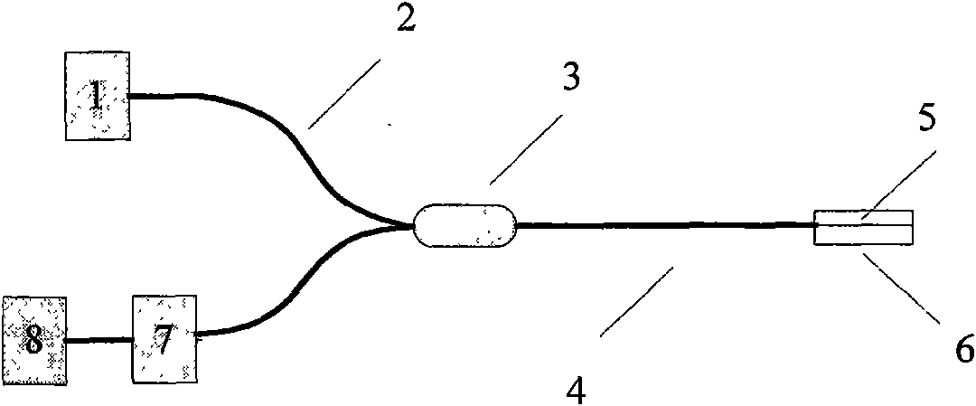
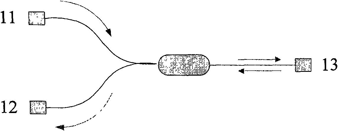
[0030] Depend on figure 1 It can be seen that the concrete composition of the long-period fiber grating steel bar corrosion sensor system of the present invention is that broadband light source 1 (can adopt LG150 type broadband light source), enters Y-type fiber coupler 2 (such as figure 2 shown) to the input end of the Y-type fiber coupler 2, and then through the coupler joint 3, through the sensing fiber 4 to the terminal reflective long-period fiber grating steel bar corrosion sensor probe 5, and the environment to be measured in Cl - The content interaction produces the coupling effect between the core and the cladding, and after passing through the reflective metal film on the end face of the core in the probe 5, the reflected light is formed and enters the spectrometer 7 through the reflective end of the Y-shaped fiber coupler 2 (AQ6317 spectrometer can be used ), and then processed by the computer 8 to output the relationship curve between the reflected light intensi...


PUM


Abstract

The invention relates to a method for monitoring steel bar corrosion state in concrete by stages and a sensor, and belongs to the field of tests of civil engineering sensors. The method comprises two stages for monitoring the steel bar corrosion state, namely an initial stage of steel bar corrosion for monitoring Cl content and a stage for monitoring the content of liquid rust nearby the steel bar during rusting; therefore, the method prolongs the effective working time of a steel bar corrosion sensor. The sensor comprises a sleeve, a fiber bracket and an LPFG sensing probe, wherein the sleeve is provided with a hole; the fiber bracket is arranged in the sleeve; the LPFG sensing probe is freely and straight arranged on the fiber bracket; and a monitoring medium is filled in the sleeve.

Description

technical field [0001] The invention relates to a stage-by-stage monitoring method and a sensor for the corrosion state of steel bars in concrete, belonging to the field of civil engineering sensor testing. Background technique [0002] Long-period fiber grating (hereinafter referred to as LPG) is a sensing grating based on the coupling theory of core guided mode and cladding mode. concentration. The biological and chemical sensing technology based on this coupling theory has been widely used in many biochemical research fields such as the measurement of antigen content in blood, the identification of protein substances, drug screening, the detection of solution concentration, and the determination of the degree of degradation of sewage. [0003] With the wide application of reinforced concrete structures in large-scale construction projects, the corrosion of steel bars in concrete has become the most important disaster that threatens the durability of reinforced concrete s...

Claims


Application Information

Patent Timeline
IPC IPC(8): G01N21/88G01N21/59G01N21/41
Inventor 曾捷刘宏月梁大开王晓洁胡兴柳
Owner NANJING UNIV OF AERONAUTICS & ASTRONAUTICS
Why Eureka
Eureka Blog
Learn More