
Sub-carrier mapping method

A technology of subcarrier mapping and carrier mapping, which is applied in the direction of error prevention/detection, frequency diversity, network planning, etc. using the return channel, which can solve the problem of not being able to play both centralized and distributed mapping, and achieve high throughput

Inactive Publication Date: 2009-10-28
XUZHOU MASTER MECHANICAL TECH CO LTD
View PDF0 Cites 25 Cited by
  • Summary
  • Abstract
  • Description
  • Claims
  • Application Information

AI Technical Summary

Problems solved by technology

The existing subcarrier mapping methods can only use one subcarrier mapping method at the same time, and cannot take advantage of both centralized mapping and distributed mapping at the same time

Method used


Image

  • Sub-carrier mapping method
  • Sub-carrier mapping method
  • Sub-carrier mapping method

Examples


Embodiment Construction

[0023] The technical scheme of the invention solves the problem that traditional subcarrier mapping cannot support multiple subcarrier mapping methods at the same time, and can simultaneously meet the data transmission requirements of frequency-selective and frequency-non-selective users, and is more flexible.

[0024] The subcarrier mapping method will be described in detail below with reference to the accompanying drawings and in combination with preferred embodiments of the present invention, taking a broadband cellular wireless communication system as an example.

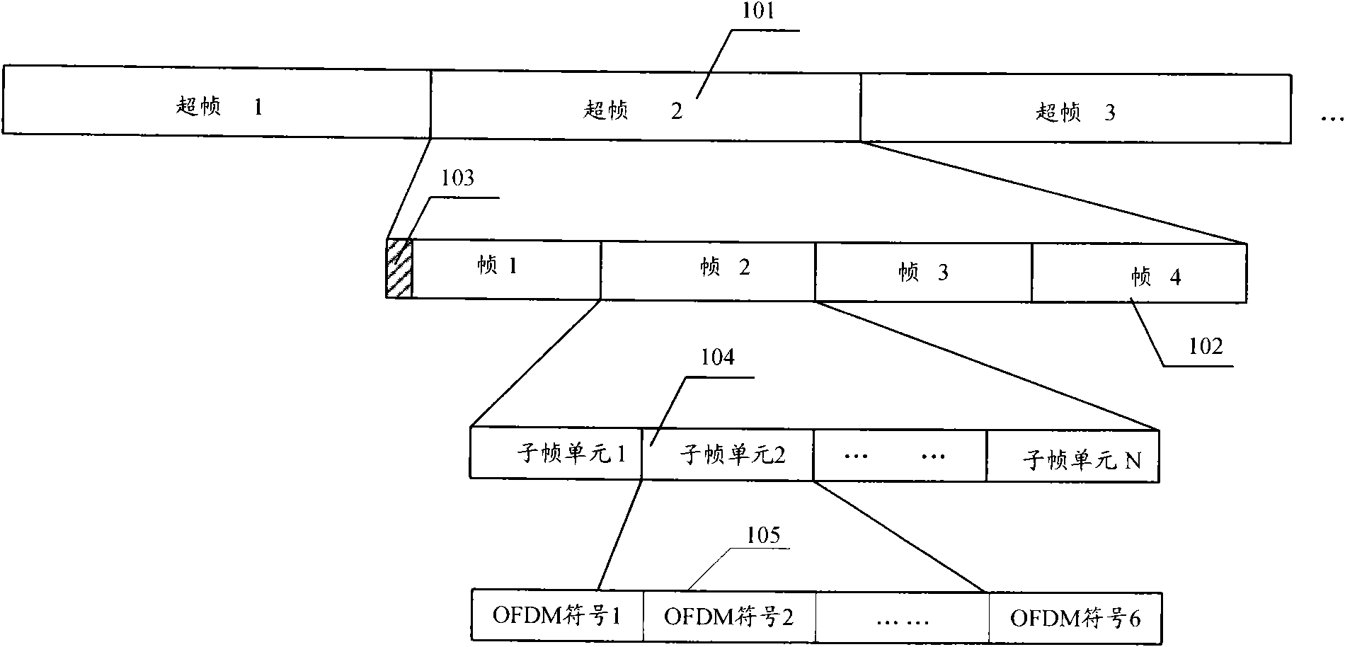
[0025] Such as figure 1 As shown, it is a schematic composition diagram of a frame structure related to the control channel in the present invention. The superframe 101 is composed of four unit frames 102, and the superframe control information 103 is located on several symbols at the beginning of the superframe. The unit frame 102 is composed of 8 subframe units 104, and the subframe unit 104 is divided into a ...


PUM


Abstract

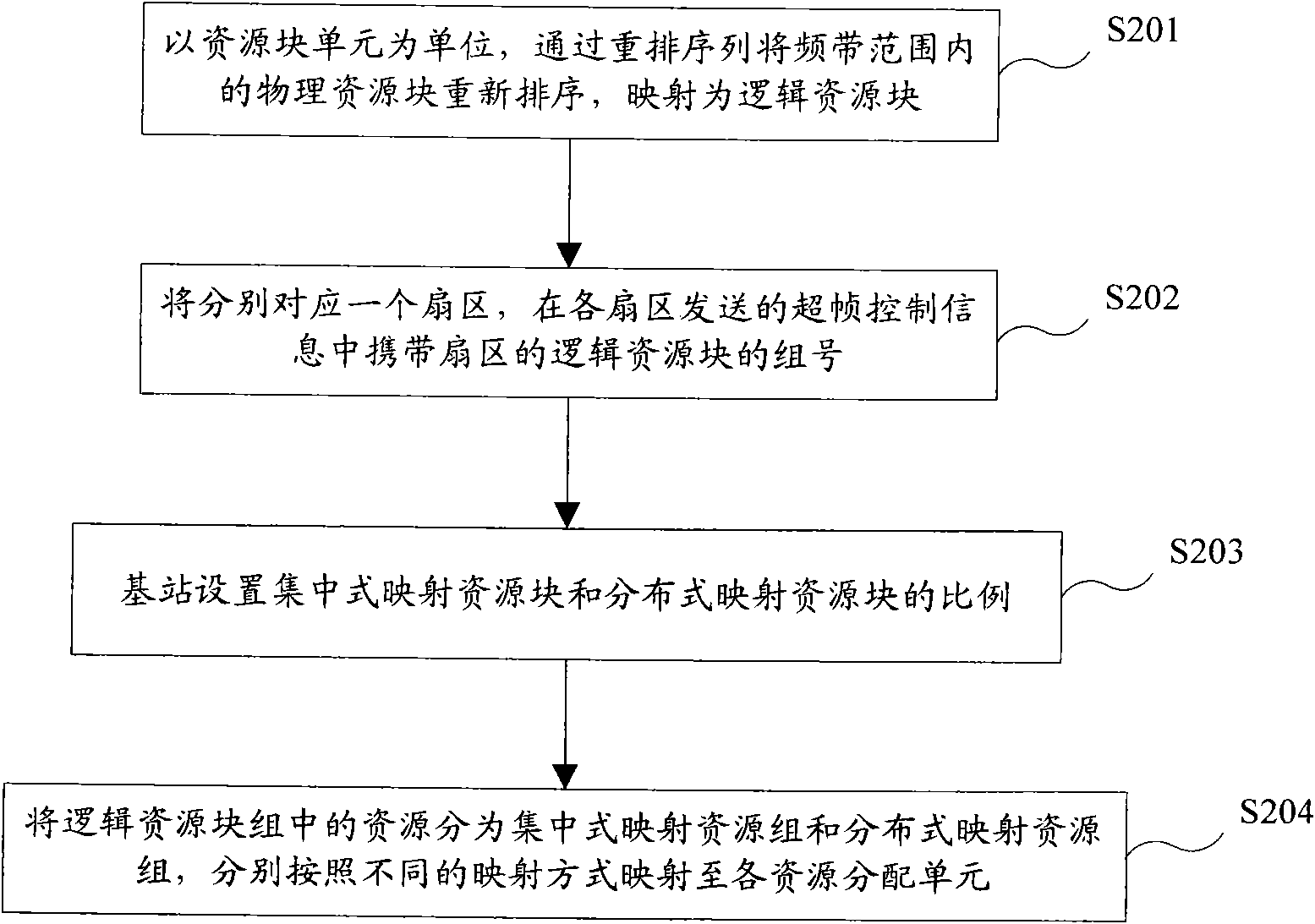
The invention discloses a sub-carrier mapping method which comprises: with the set resource block elements as units, physical resource blocks in the frequency band range are rearranged according to a rearrangement sequence so as to be mapped into logical resource blocks; the mapped logical resource blocks in the frequency band range are grouped by a base station, each grouped logical resource block respectively corresponds to one sector, and the superframe control information sent by each sector carries a logical resource block group number which corresponds to the sector; and in each sector of the base station, the resources in the logical resource block group are divided into a centralized mapping resource group and a distributed mapping resource group according to the set proportion, wherein continuous sub-carriers in each resource block unit in the centralized mapping resource group are directly mapped to each resource allocation unit, and after being rearranged through a permutation matrix, all sub-carriers in the distributed mapping resource group are sequentially mapped to each resource allocation unit. The technical scheme of the invention can ensure that users who move quickly and slowly can obtain high throughput.

Description

technical field [0001] The invention relates to a broadband wireless communication technology in the field of mobile communication, in particular to a subcarrier mapping method. Background technique [0002] In a wireless communication system, a base station refers to a device that provides services to a terminal. The base station communicates with the terminal through the uplink and downlink. The downlink refers to the direction from the base station to the terminal, and the uplink refers to the direction from the terminal to the base station. Multiple terminals can simultaneously send data to the base station through the uplink, and can also receive data from the base station through the downlink at the same time. [0003] Next-generation broadband mobile communication systems such as Mobile WiMAX (Worldwide Interoperability for Microwave Access, UMB (Ultra Mobile Broadband, Ultra Mobile Broadband) and LTE (3GPP Long Term Evolution, 3GPP Long Term Evolution) all use OFDMA...

Claims


Application Information

Patent Timeline
IPC IPC(8): H04W16/24H04W72/08H04B7/12H04L1/16
Inventor 李艳
Owner XUZHOU MASTER MECHANICAL TECH CO LTD
Learn More