
Semimetal ceramic matrix brake pad and manufacturing method thereof

A brake pad and ceramic-based technology, applied in the field of brake pads, can solve the problems of reduced service life of brake pads, increased high-temperature wear of materials, and high-temperature wear performance that are prone to cracks, achieving high safety and reliability, high temperature resistance and The effect of improved service life and simple and reliable preparation method

Inactive Publication Date: 2009-11-04
CENT SOUTH UNIV +1
View PDF0 Cites 11 Cited by
  • Summary
  • Abstract
  • Description
  • Claims
  • Application Information

AI Technical Summary

Problems solved by technology

At present, the mainstream automobile brake pads on the market are all made of semi-metal or metal-less resin-based friction materials. When the car is in continuous or emergency braking, the temperature on the surface of the brake pads and brake discs is as high as 500-700 ° C. Due to the resin-based brake pads Poor temperature resistance, it will decompose and release water, gas, oil, etc. at high temperature, and form a thin film on the friction surface, making dry friction into mixed friction or wet friction, the friction coefficient is significantly reduced, and there is a hidden danger of brake failure. Due to the large amount of thermal decomposition of the resin, its bonding effect is reduced, and the high temperature wear of the material is aggravated, resulting in a significant reduction in the service life of the brake pads
At present, some ceramic automobile brake pads on the market use a large amount of ceramic fibers instead of traditional steel fibers. Although their braking comfort performance (including noise, ash falling, and matching with the pair, etc.) has been significantly improved, resin is still used as the main material. Adhesives, which lead to problems such as high-temperature thermal recession, easy cracks and poor high-temperature wear performance at high temperatures

Method used


Image

  • Semimetal ceramic matrix brake pad and manufacturing method thereof
  • Semimetal ceramic matrix brake pad and manufacturing method thereof

Examples

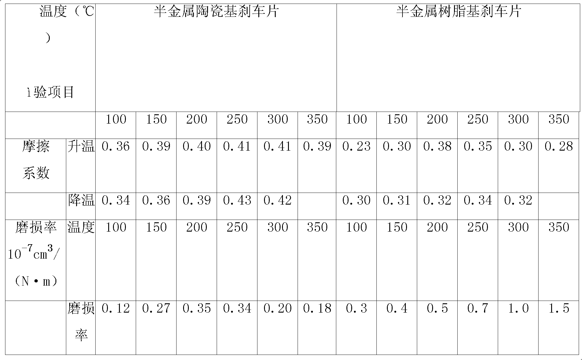

Embodiment Construction

[0022] The present invention will be further described below in combination with specific embodiments.

[0023] Description of the formula of the semi-metallic ceramic base brake pad provided by the invention

[0024] Ceramic binder 10~20(wt.%) Resin / rubber 5~10(wt.%)

[0025] Steel fiber 30~40(wt.%) Copper fiber, ceramic or mineral fiber 5~10(wt.%)

[0026] Graphite 5~10(wt.%) Antimony sulfide 3~8(wt.%)

[0027] Chromite 2~5(wt.%) Organic friction powder 2~5(wt.%)

[0028] Barite 10~20(wt.%) Petroleum coke 5~10(wt.%).

[0029] In this formula system, the ceramic binder mainly refers to the modified aluminum and silicate inorganic high-temperature binder, which can significantly improve the temperature resistance of the material, reduce the wear of the material at high temperature, and at the same time make the material Form a porous structure, increase braking smoothness, and reduce braking noise. In order to continue to use the molding process and production equipment o...


PUM


Abstract

The invention discloses a semimetal ceramic matrix brake pad, the material formulation of which is as follows by weight percentage: 15-30 parts of bonding matrices, 25-50 parts of reinforcing fibers, 10-20 parts of regulators with frictional properties, and 10-30 parts of filling materials; wherein, the bonding matrix mainly takes modified sodium aluminosilicate as inorganic HTAs (high temperature adhesives) and a little of phenolic resin and rubber as organic low-and-medium temperature accessorial adhesives, and the weight ratio of an inorganic ceramic adhesive to an organic adhesive is equal to 5:1; the reinforcing fiber mainly takes steel fiber, cooper fiber, ceramics or mineral fiber as an accessorial reinforcing fiber, and the weight ratio of the steel fiber to the accessorial reinforcing fiber is 10:1; the regulators with frictional properties comprise chromite, graphite and friction dust; the filling materials comprise oil coke and baria. The semimetal ceramic matrix brake pad prepared in the invention is safe and reliable, and the manufacturing method is simple and reliable.

Description

technical field [0001] The invention relates to a brake pad, in particular to a low metal ceramic matrix composite brake pad used in an automobile brake system, and also relates to a preparation method of the automobile brake pad. Background technique [0002] Automobile brake pads are the key components of Class A of the automobile braking system, and their performance is directly related to the safety and reliability of automobile operation. At present, the mainstream automobile brake pads on the market are all made of semi-metal or metal-less resin-based friction materials. When the car is in continuous or emergency braking, the temperature on the surface of the brake pads and brake discs is as high as 500-700 ° C. Due to the resin-based brake pads Poor temperature resistance, it will decompose and release water, gas, oil, etc. at high temperature, and form a thin film on the friction surface, making dry friction into mixed friction or wet friction, the friction coefficie...

Claims


Application Information

Patent Timeline
IPC IPC(8): F16D69/02C04B35/80C22C49/14B22F3/02C21D9/00
Inventor 刘伯威黄伯云熊翔贺云果刘美玲宋晓萍杨阳
Owner CENT SOUTH UNIV
Learn More