Egr valve device
A technology for exhausting gas and driving devices, which is used in exhaust gas recirculation, valve device, fluid pressure actuating device, etc. Good maintenance of sealing, good assembly, and uncomplicated structure
- Summary
- Abstract
- Description
- Claims
- Application Information
AI Technical Summary
Problems solved by technology
Method used
Image
Examples
no. 1 approach
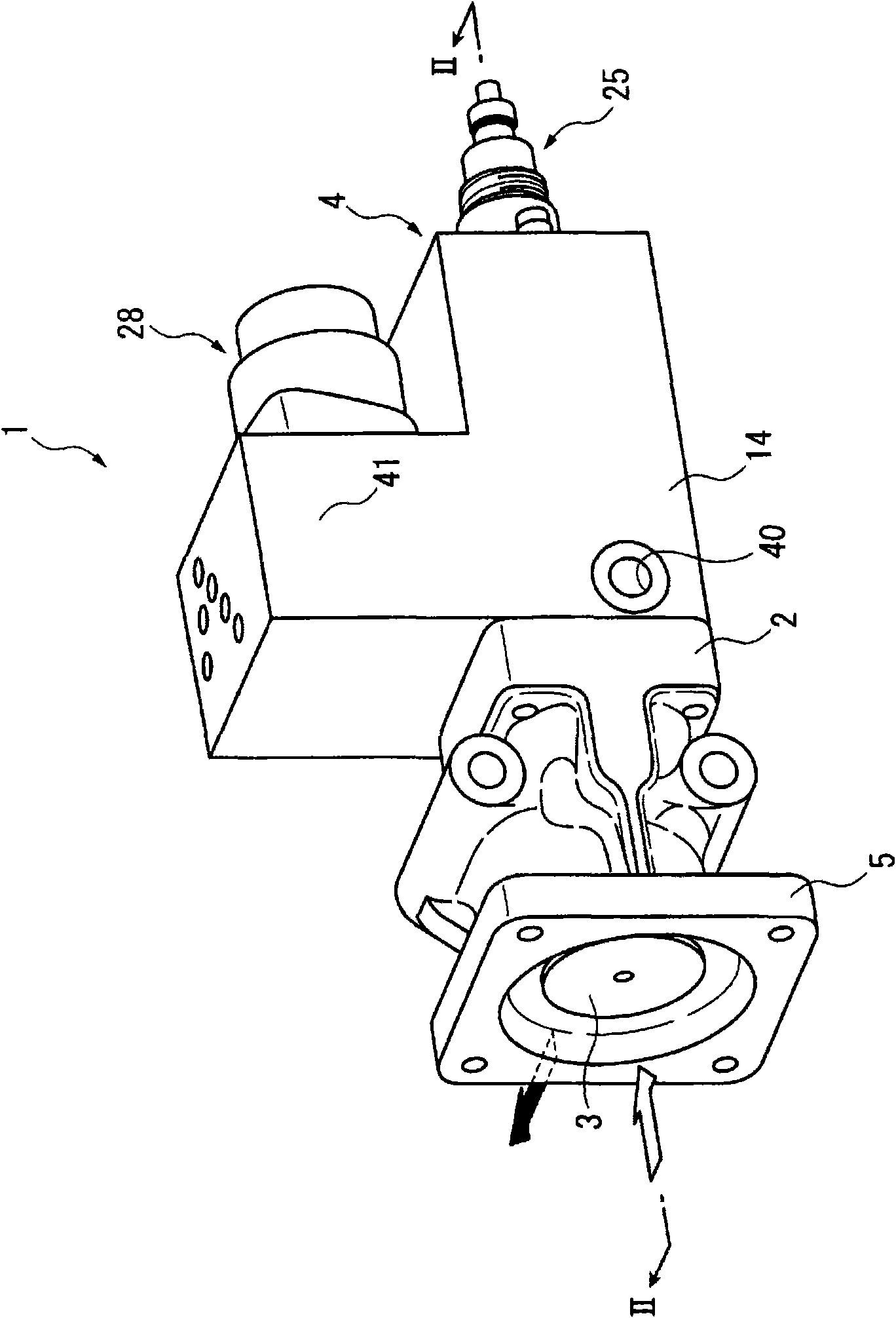
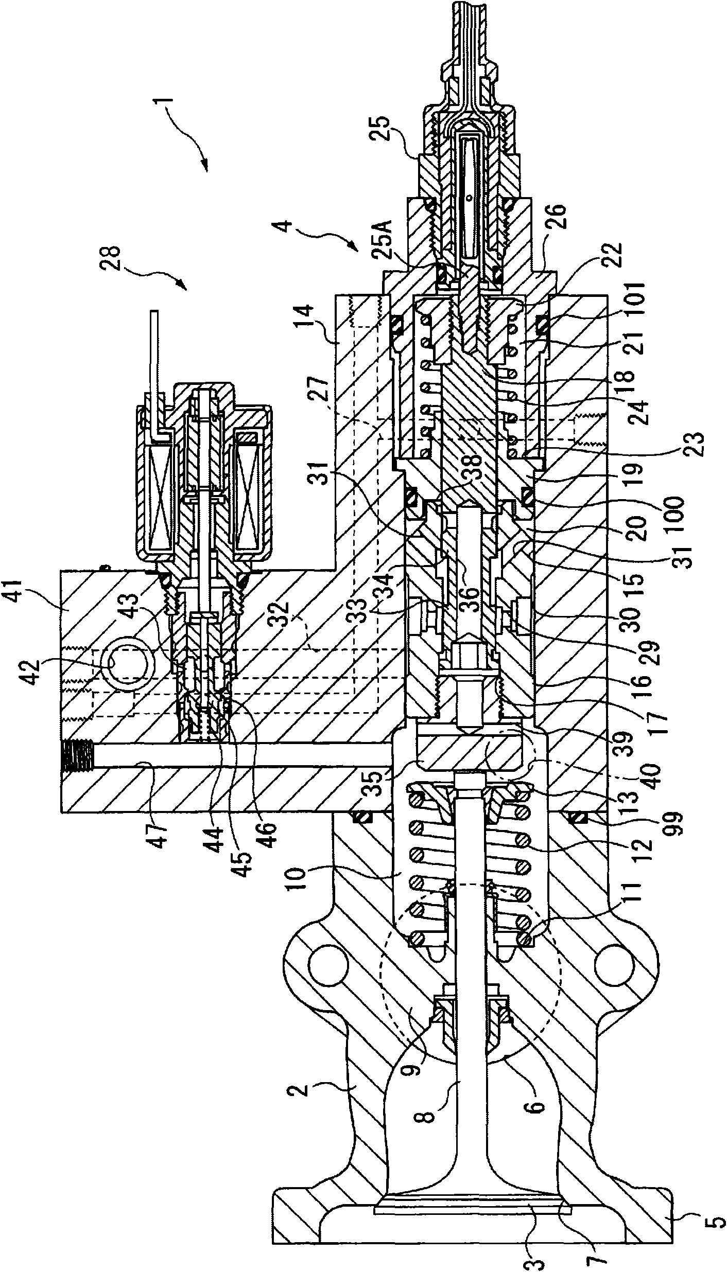
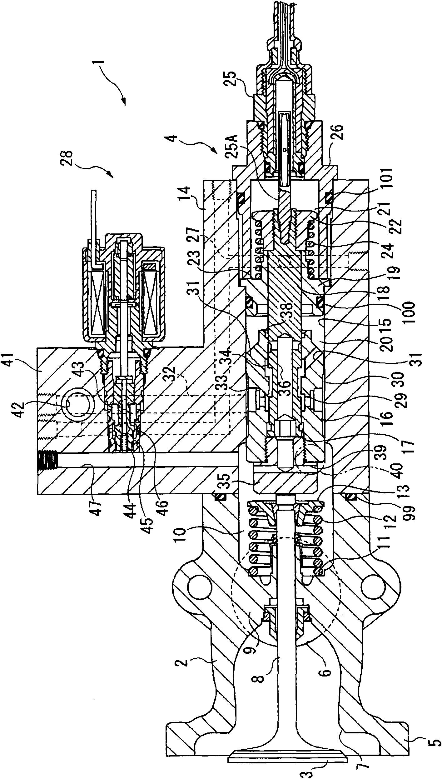
[0059] figure 1 It is a perspective view showing the appearance of the EGR valve device 1 according to this embodiment, which shows a state in which the poppet valve 3 as a valve body is closed; figure 2 is a cross-sectional view of the EGR valve device 1, namely figure 1 The II-II line view. Starting from the second embodiment described later, the same reference numerals are assigned to the same components as those in the first embodiment described below, and descriptions thereof are omitted or simplified.
[0060] exist figure 1 Here, the EGR valve device 1 is a device constituting an EGR system mounted on a diesel engine with a variable turbocharger (not shown). More specifically, the EGR system is composed of an EGR pipe connecting the exhaust manifold and the intake pipe, an EGR cooler installed in the middle of the EGR pipe, and an EGR valve installed on the downstream side of the EGR cooler, that is, on the outlet side of the EGR pipe. device 1, and a controller fo...
no. 2 approach 〕
[0094] Figure 4 A second embodiment of the present invention is shown. This embodiment is very different from the first embodiment in terms of the shape of the servo piston 16 and the absence of a valve spring.
[0095] In the servo piston 16 of the present embodiment, the pressure port 29 is used as a boundary, and the side of the hydraulic chamber 20 is a large-diameter portion 48 , and the side of the poppet valve 3 is a small-diameter portion 49 . Therefore, in the cylinder chamber 15 , the portion where the large-diameter portion 48 slides and the portion where the small-diameter portion 49 slides have different inner diameters of the cylinder chamber 15 . In such a configuration, the large diameter portion 48 has a larger pressure receiving area for the pressure oil flowing into the pressure port 29 than the small diameter portion 49 .
[0096] Therefore, when the pressure oil in the hydraulic chamber 20 is discharged to return the servo piston 16 to the hydraulic cha...
no. 3 approach 〕
[0099] Figure 5 A third embodiment of the present invention is shown. A major feature of this embodiment is that a butterfly valve 51 is used as a valve body. The butterfly valve 51 is rotatably accommodated in an exhaust passage of a valve sleeve 52 provided in the middle of the EGR piping. The drive shaft 53 of the butterfly valve 51 protrudes to the outside of the valve housing 52 . An arm 54 extending in a direction perpendicular to the axis thereof is attached to an end of the drive shaft 53 , and the arm 54 rotates integrally with the butterfly valve 51 .
[0100] A connecting pin 55 is provided at one end of the arm 54, and a mounting portion of the arm 54 and the drive shaft 53 is sandwiched between the one end and the other end, and one end of a link 56 is rotatably connected to the connecting pin 55. side. The other end of the connecting rod 56 is rotatably connected to a connecting pin 57 provided on the seal member 35 on the servo piston 16 side. Also, one en...
PUM
 Abstract
Description
Claims
Application Information
 - R&D
- Intellectual Property
- Life Sciences
- Materials
- Tech Scout
- Unparalleled Data Quality
- Higher Quality Content
- 60% Fewer Hallucinations
Browse by: Latest US Patents, China's latest patents, Technical Efficacy Thesaurus, Application Domain, Technology Topic, Popular Technical Reports.
© 2025 PatSnap. All rights reserved.Legal|Privacy policy|Modern Slavery Act Transparency Statement|Sitemap|About US| Contact US: help@patsnap.com


