Sensor instrument system including method for detecting analytes in fluids

A technology for detecting sensors and sensors, which is applied in the field of sensor instrument systems for analytes, and can solve problems such as sensor inconsistency, difficulty in making and using instruments, and complex structures

Active Publication Date: 2009-11-18
孙一慧 +1
View PDF6 Cites 19 Cited by
  • Summary
  • Abstract
  • Description
  • Claims
  • Application Information

AI Technical Summary

Problems solved by technology

Although sensor research along this scheme has made great strides in the past, it still has the disadvantages of using multi-sensor schemes
These disadvantages include: a large number of sensors are required to generate the type-differentiated information map of the analyte; the complex structure of the sensor leads to inconsistency in the production of the sensor; Humidity interference; slow sensitivity; necessary expensive instruments and severely restricted operating conditions
Second, the polymer film material has an aging effect, which affects the long-term stability of the sensor
Third, it is also a difficult problem to obtain the repeatability of the polymer material film placed on the sensor in production
However, the electric resonance phenomenon of Pena's device must be in the frequency range of 100 megacycles to 500 megacycles to be possible
This high frequency limitation brings great difficulties to the production and use of the instrument

Method used


Image

  • Sensor instrument system including method for detecting analytes in fluids
  • Sensor instrument system including method for detecting analytes in fluids
  • Sensor instrument system including method for detecting analytes in fluids

Examples


example

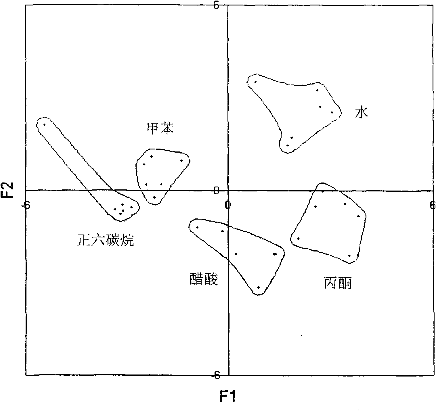
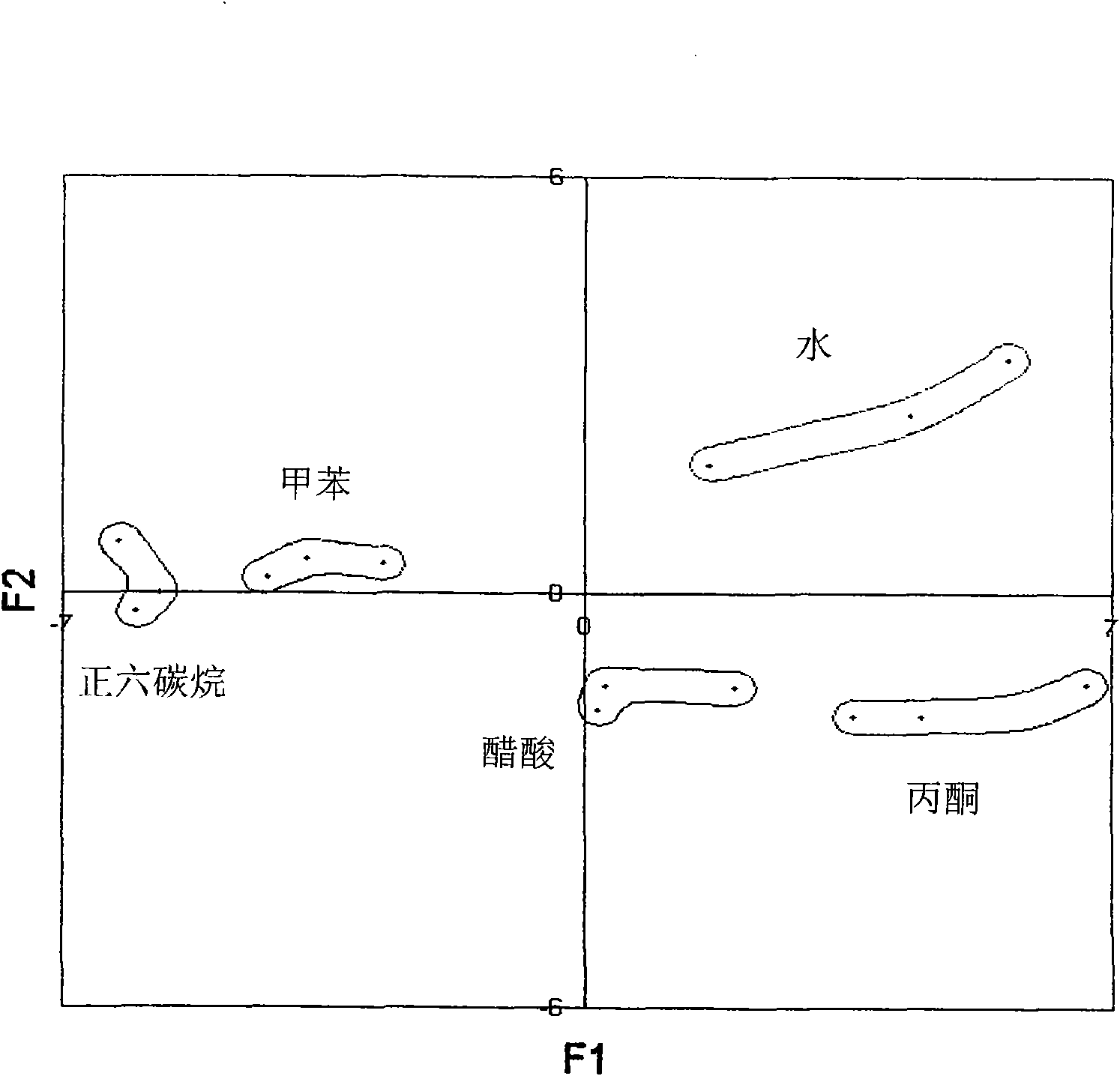
[0185] Disclosed below are examples and experimental situations related to the core technology of the present invention, that is, a single sensor using the operating principles of AC frequency sweep and vector analysis. This example is provided only as an illustration of the present invention, not as a limitation or constraint on the present invention.

[0186] A pair of electrodes as the simplest sensor is made of a pure gold circular wire. The electrodes are 12 mm long and the electrode spacing is about 1 mm. A standard coaxial cable is used to connect the electrode to an AC current analyzer, such as the Agilent 4294 Electrical Impedance Meter: Agilent 4294A (Agilent: Agilent; Palo Alto, CA, USA). Before testing the sample, the electrode is electrically calibrated. The method of AC frequency scanning and vector analysis is applied in the test of electrical impedance, so that at each scanned frequency, two electrical properties of different combinations of electrical impeda...

Embodiment approach

[0232] If you choose the first implementation, that is, the electrical properties of the detected analytes are analyzed by the sensor instrument at the detection site, so that after the detection is completed, the detection software will automatically display many methods including principal component analysis. Analytical application software to identify each analyte.

[0233] The fourth part is the option of how to deliver the detected information including the results of the identified analytes. It includes the scheme of automatically outputting the results after the corresponding selected implementation scheme is completed, and the scheme of manual control outputting after the user of the instrument enters an instruction to allow the output.

[0234] The application software that starts this detection is after being placed in a mark " operation " that is placed at the end of software and is clicked, and like this also just started sensor instrument 18 simultaneously and mak...


PUM


Abstract

A sensor instrument system and a method for detecting and identifying analytes in fluids of a region comprising a local sensor instrument and remote central station are disclosed. The instrument is comprised of a core technology employing a single sensor having two electrodes operated by an electrical frequency sweeping to generate two sets of patterned electrical information from a single measurement, a data transmission module and a GPS receiver module. The central station connects to a network means connected to a plurality of local receiving sites equipped with including the respective transceivers, so that the local analyte electrical information and geographic position information transmitted by the instrument can be wirelessly and remotely received and processed by the central station. The core technology is further comprised of a reference sensor for eliminating background influence, a temperature programming to control adsorption and desorption of analytes, and usage of all kinds of adsorbent materials having chemical selectivity including the hydrogen selectivity to enhance detection and identification of analytes in fluids.

Description

[0001] Patent application documents related to this application [0002] The present application is a continuation of US Application Serial No. 10 / 238,794; now US Patent No. 7,465,425, filed September 9, 2002, with new structures added. field of invention [0003] The invention relates to the field of sensor instruments, in particular to sensor instrument systems and methods for detecting analytes in fluids. Background technique [0004] Sensor instruments are widely used to detect analytes in fluids. The following are references related to the technology of the present invention. [0005] 1. U.S. Patent No. 4,887,455 entitled "Gas Sensor" granted to Payne et al. on December 9, 1989 (hereinafter referred to as Payne's '455 patent); [0006] 2. U.S. Patent No. 5,571,401 granted to Lewis on November 5, 1996, et al., entitled "Sensor Group for Detecting Analytes in Fluids" (hereinafter Lewis' 571 patent); [0007] 3. US Patent No. 6,314,724 was granted to Lewis et al. on No...

Claims


Application Information

Patent Timeline
Patent Type & Authority Applications(China)
IPC IPC(8): G01N27/00G01N27/12
Inventor 孙一忠
Owner 孙一慧
Why Eureka
Try Eureka