Supercharge Your Innovation With Domain-Expert AI Agents!

Cylindrical single-phase permanent magnet linear synchronous motor with parallel magnetic circuits and propulsion control system thereof

A single-phase permanent magnet, cylindrical technology, applied in the direction of propulsion systems, electric components, electrical components, etc., can solve the problems of difficult processing of permanent magnet brackets, large secondary pole distance requirements, complex processing technology, etc., and achieve structural High strength and reliability, large eddy current solution, broad application prospects

Active Publication Date: 2009-11-18
HARBIN INST OF TECH
View PDF0 Cites 6 Cited by
  • Summary
  • Abstract
  • Description
  • Claims
  • Application Information

AI Technical Summary

Problems solved by technology

[0004] The present invention solves the complex processing technology and high cost of the existing linear motor armature core made of silicon steel sheets, such as the use of a solid core structure will produce a large eddy current loss; at the same time, there is also a permanent magnet bracket that is difficult to manufacture and process , the problem of large secondary pole distance requirements, and the shortcomings of the existing motor drive control system, which are large in size and difficult to integrate, the proposed parallel magnetic circuit cylindrical single-phase permanent magnet synchronous linear motor and its drive control system

Method used


Image

  • Cylindrical single-phase permanent magnet linear synchronous motor with parallel magnetic circuits and propulsion control system thereof
  • Cylindrical single-phase permanent magnet linear synchronous motor with parallel magnetic circuits and propulsion control system thereof
  • Cylindrical single-phase permanent magnet linear synchronous motor with parallel magnetic circuits and propulsion control system thereof

Examples


specific Embodiment approach 1

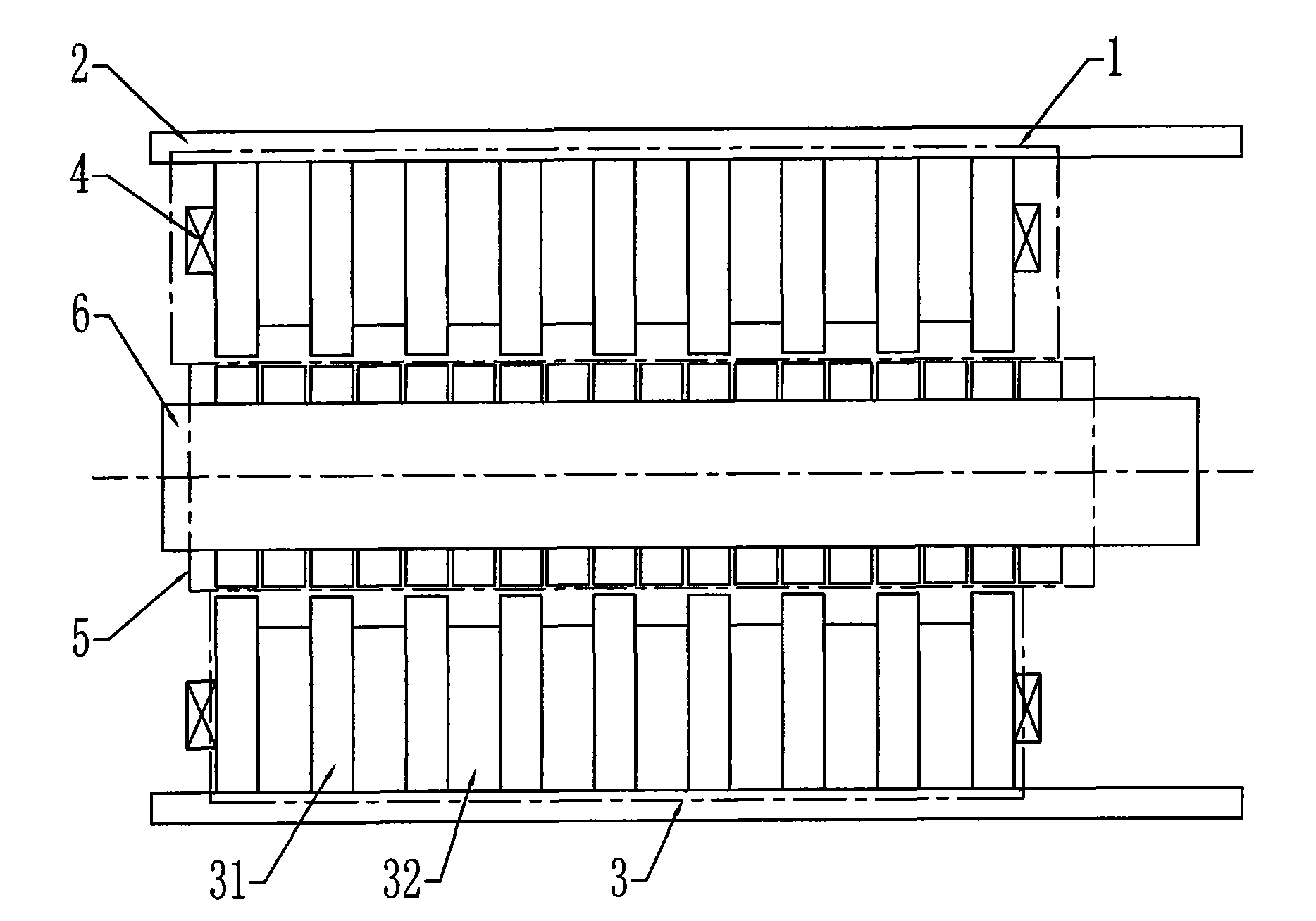
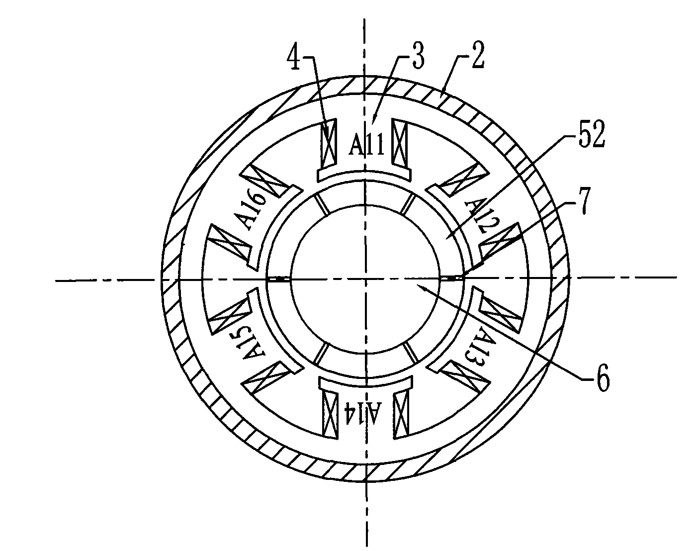
[0009] Specific implementation mode one: combine figure 1 and figure 2 Describe this embodiment, this embodiment includes primary, secondary, air gap and mover support leaf spring; secondary includes permanent magnet array 5 and shaft tube 6; permanent magnet array 5 is fixedly arranged on shaft tube 6; primary includes electrical Armature 1 and casing 2; armature 1 includes armature core 3 and armature winding 4; armature core 3 includes i+1 annular core segments 31 and i core segment spacer rings 32, where i is a positive integer ; The i+1 annular iron core segments 31 and i iron core segment spacer rings 32 are arranged at intervals along the axial direction; the sum of the axial thicknesses of an annular iron core segment 31 and an iron core segment spacer ring 32 is equal to 2τ p , where τ p is the pole pitch of the permanent magnet; the inner circumference of each armature core 3 is evenly opened with 2n slots along the axial direction, wherein n is a positive intege...

specific Embodiment approach 2

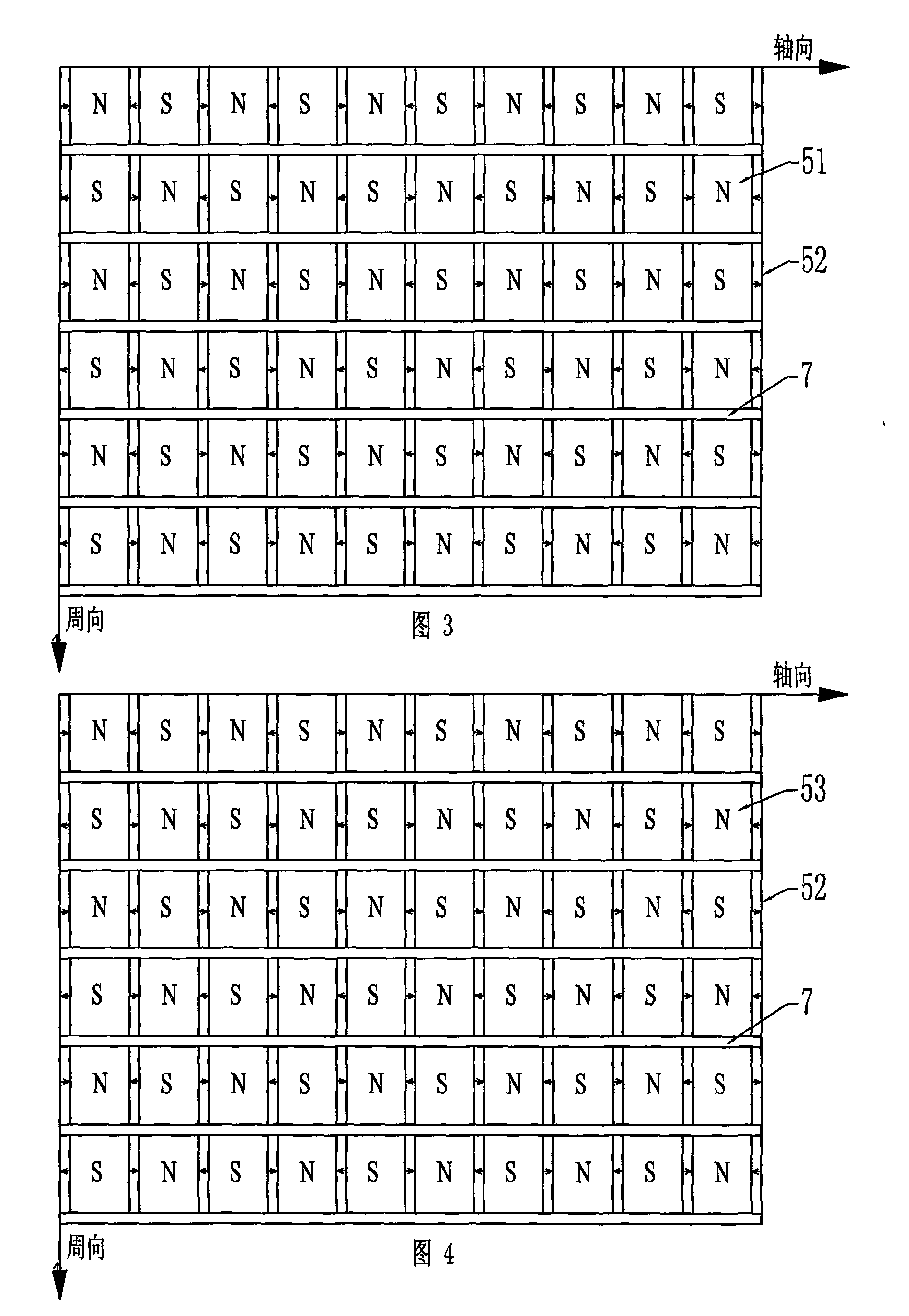
[0010] Specific implementation mode two: combination image 3 Describe this embodiment, the difference between this embodiment and the specific embodiment is that the secondary also includes 2n non-magnetic spacers 7, and the permanent magnet array 5 includes m sector-shaped permanent magnets 52 and m-1 tile-shaped permanent magnets 51 , sector-shaped permanent magnets 52 are axially magnetized, tile-shaped permanent magnets 51 are radially magnetized, and m sector-shaped permanent magnets 52 and m-1 tile-shaped permanent magnets 51 are arranged alternately along the axial direction to form a row of permanent magnet strips , 2n columns of permanent magnet strips and 2n non-magnetic spacer strips 7 are arranged alternately along the circumferential direction, and the magnetization directions of the two adjacent sector permanent magnets 52 in the axial or circumferential direction are opposite; The magnetization directions of the two tile-shaped permanent magnets 51 are opposite...

specific Embodiment approach 3

[0011] Specific implementation mode three: combination Figure 4 Describe this embodiment, the difference between this embodiment and the specific embodiment is that the secondary also includes 2n non-magnetic spacers 7, and the permanent magnet array 5 includes m sector-shaped permanent magnets 52 and m-1 tile-shaped magnetic permeable yokes 53. Sector-shaped permanent magnets 52 are axially magnetized. m sector-shaped permanent magnets 52 and m-1 tile-shaped magnetic yokes 53 are arranged alternately in the axial direction to form a row of permanent magnet strips, and 2n columns of permanent magnet strips are connected to 2n non-magnetic strips. The magnetic spacer bars 7 are arranged alternately along the circumferential direction, and the magnetization directions of the two sector-shaped permanent magnets 52 adjacent to each other in the axial or circumferential direction are opposite. Other compositions and connection methods are the same as those in Embodiment 1.


PUM


Abstract

The invention discloses a cylindrical single-phase permanent magnet linear synchronous motor with parallel magnetic circuits and propulsion control system thereof, relating to the field of motor. The invention solves the problems of complex processing technique, high cost and big eddy current loss of the armature core of the existing linear motor, as well as the shortages of big volume and hard integration of the existing motor propulsion control system. The armature core of the motor comprises i+1 circular-ring core stacks and i spacer rings of core stacks, wherein, i+1 circular-ring core stacks and i spacer rings of core stacks are respectively arrayed with intervals along axialdirection; the axial thickness sum of one circular-ring core stack and one spacer ring of the core stack equals to 2taup, wherein taup is permanent magnet polar distance; the inner circumference of each armature core is evenly provided with 2n tooth spaces along axial direction, and n is signless integral; each loop of armature winding winds on each tooth of the armature core, the loops on the adjacent teeth of the armature core have reverse winding direction, and all the loops on the teeth of the armature core are connected in series to form the armature winding. The invention can be applied in straight-line compressor systems and Stirling engine systems.

Description

technical field [0001] The invention specifically relates to a permanent magnet synchronous linear motor and its drive control system. Background technique [0002] A common structure of short-stroke linear motors is as follows: Figure 9 shown. The moving part of the motor is a permanent magnet, which is connected with a spring through a mover bracket. The working magnetic field consists of two parts, one is the alternating magnetic field generated by the excitation coil, and the other is the constant magnetic field generated by the permanent magnet. The structure is ring-shaped, and the outer iron yoke and the inner iron yoke are fixed parts. The permanent magnet is installed on a non-magnetic and non-conductive support. The polarity of the outer circumferential surface of the permanent magnet is the same. When the winding is fed with an alternating current, the winding The magnetic field interacts with the magnetic field of the permanent magnet to produce an alternating...

Claims


Application Information

Patent Timeline
Patent Type & Authority Applications(China)
IPC IPC(8): H02K41/03
Inventor 寇宝泉刘奉海贵献国吴红星
Owner HARBIN INST OF TECH
Features
  • R&D
  • Intellectual Property
  • Life Sciences
  • Materials
  • Tech Scout
  • Unparalleled Data Quality
  • Higher Quality Content
  • 60% Fewer Hallucinations
Learn More