Protection device for automatic ignition and brennschluss of commercial gas furnace

A technology for automatic ignition and flameout protection, applied in household stoves/stoves, applications, household cooking utensils, etc., can solve problems such as high maintenance costs, shortened thermocouple life, inconvenience, etc., to improve the level of automatic operation and reduce power consumption. Effect

Inactive Publication Date: 2009-11-25
潘兆铿
View PDF1 Cites 4 Cited by
  • Summary
  • Abstract
  • Description
  • Claims
  • Application Information

AI Technical Summary

Problems solved by technology

This method can ensure that the solenoid valve is closed after the main burner is accidentally extinguished, but there are still three problems as follows: First, the potential of the thermocouple can only be low enough to make the solenoid valve go off when the thermocouple is cooled to a certain temperature. More than 10 seconds will cause a large amount of gas to leak during this 10 seconds, so there is a danger of explosion; second, the high-temperature flame of the main burner greatly reduces the life of the thermocouple, which is about 3 months, so its maintenance cost It is very high; the third is that when igniting, you must press the solenoid valve switch with your hand for a few seconds until the thermocouple is heated and generates enough thermoelectric potential to make the solenoid valve close before letting go, which is very inconvenient
So far, although the heat load of household gas appliances is relatively small, automatic ignition safety flameout protection has been enforced. On the contrary, due to technical reasons, automatic ignition and flameout safety have not yet been realized on high-power commercial gas appliances. protection, so safety accidents often occur

Method used


Image

  • Protection device for automatic ignition and brennschluss of commercial gas furnace
  • Protection device for automatic ignition and brennschluss of commercial gas furnace
  • Protection device for automatic ignition and brennschluss of commercial gas furnace

Examples


Embodiment 1

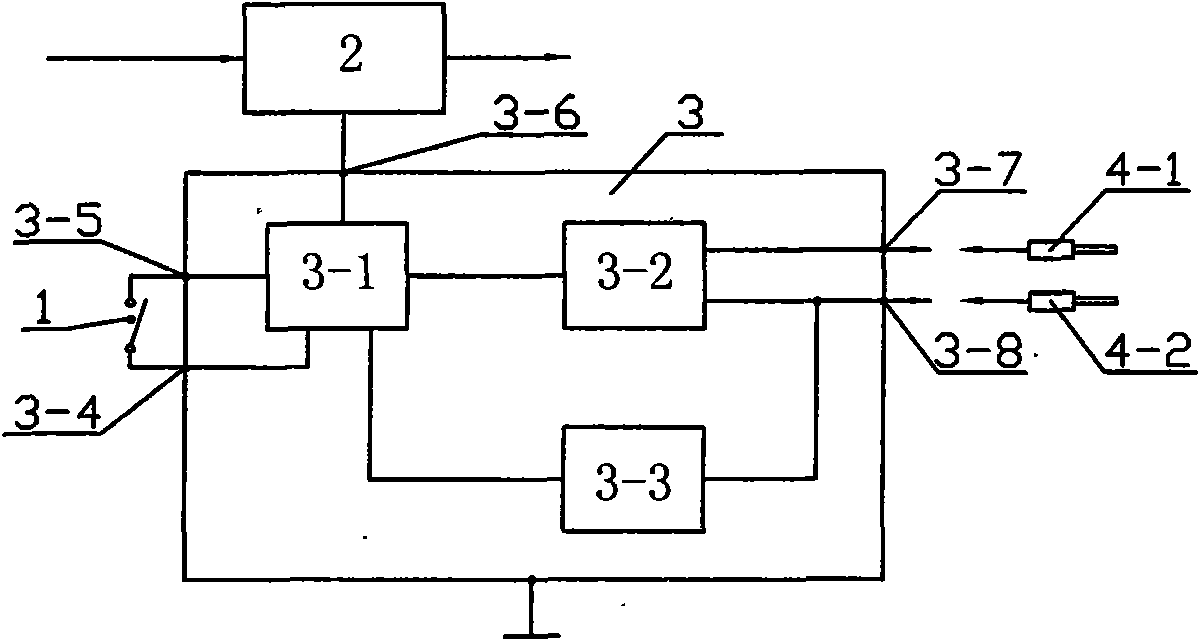
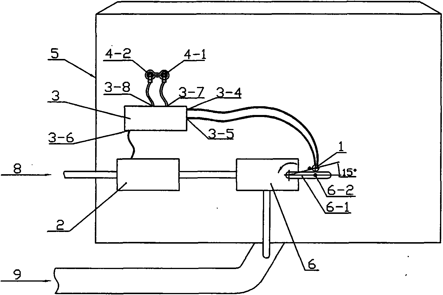
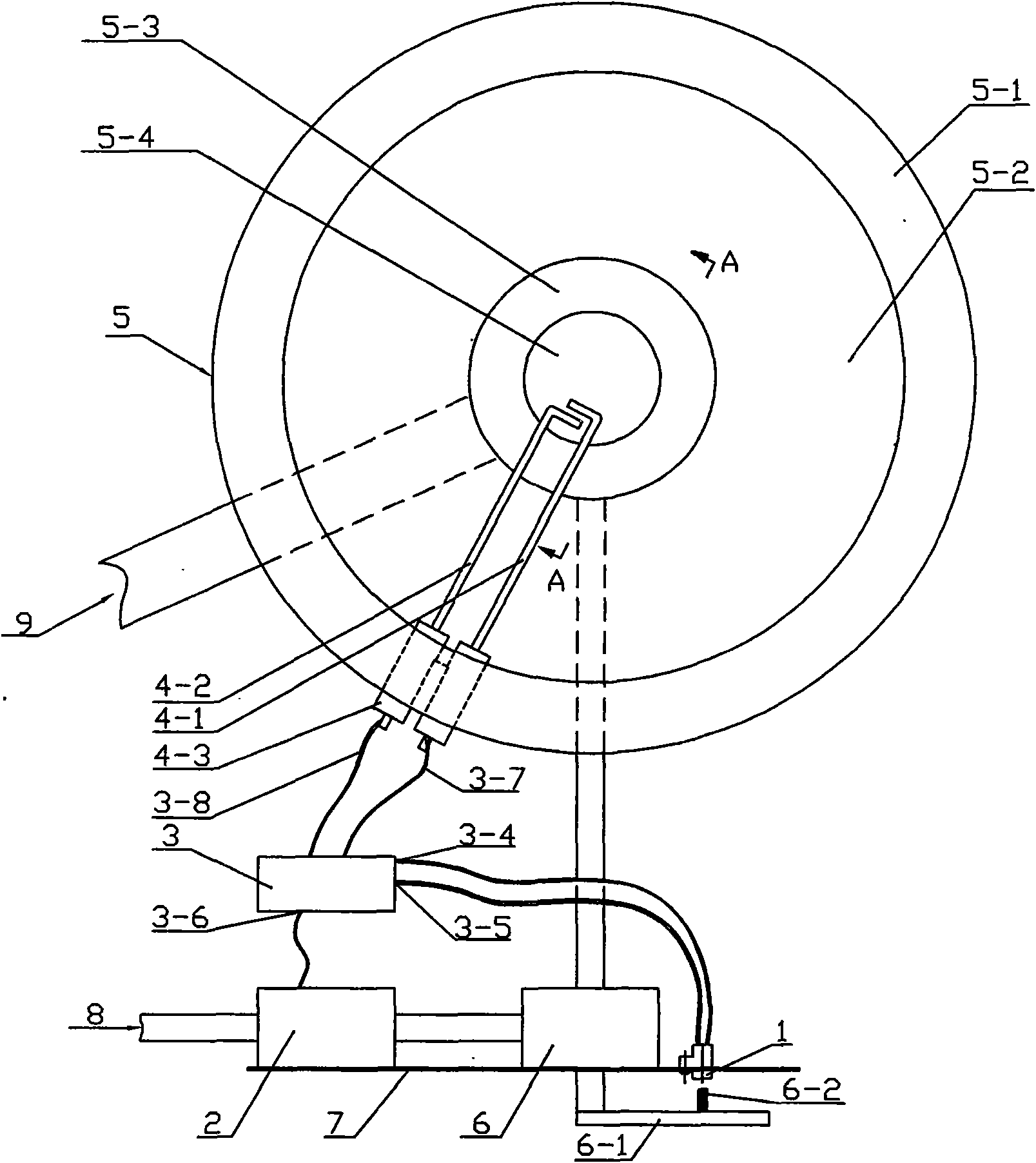
[0026] see figure 1 , figure 2 , image 3 , Figure 4 As shown, in the automatic ignition and flameout protection device for a commercial gas furnace according to an embodiment of the present invention, the commercial gas furnace includes an operation panel 7, a manual gas regulating valve 6, a burner 5-3, a furnace body 5, a refractory layer 5-1, Furnace 5-2, fire channel 5-4, commercial gas furnace automatic ignition and flameout protection device includes switch 1, gas solenoid valve 2, controller 3, the controller 3 includes main controller 3-1, continuous high-frequency high-voltage Igniter 3-2, flame ion detector 3-3, switch interface 3-4, 3-5, ignition and flame detection interface 3-7, 3-8, gas solenoid valve interface 3-6, two ignition rods 4 -1, 4-2 and the ceramic insulator 4-3 for fixing and electrical insulation at the root, the main controller 3-1 in the controller 3 is respectively connected with the continuous high-frequency high-voltage igniter 3-2 and the...

Embodiment 2

[0029] This embodiment is based on the embodiment 1, and the gas solenoid valve 2 and the controller 3 are assembled into a whole. In this embodiment, the gas solenoid valve 2 is a gas flow regulating valve. When ignited, the gas flow regulating valve 2 adjusts the gas flow by controlling the coil current to change the opening of the valve opening. The opening of the gas flow regulating valve 2 is controlled Its gas flow is about 50%-80% of the maximum value. The gas mixture is passed through the refractory layer 5-1, the furnace 5-2 and the burner 5-3 in the fire channel 5-4 of the burner 5-3 and then extends into the ignition rod 4- in the fire channel 5-4. 1, 4-2 The ionized flame generated by the metal tip is ignited. After the flame ion detector 3-3 in the controller 3 detects the ion current sent back by the ignition rod 4-2, the current provided by the main controller 3-1 makes the valve opening of the gas flow regulating valve 2 open to At the maximum, the handle 6-1...

Embodiment 3

[0031] This embodiment is a specific implementation in which the ignition rods 4-1, 4-2 are extended from the bottom of the burner 5-3 into the fire channel 5-4.

[0032] see Figure 5 As shown, the ignition rods 4-1, 4-2 pass through the inner wall of the bottom of the burner 5-3 through the ceramic insulator 4-3 and are fixed, and the ignition rods 4-1, 4-2 are about 20mm away from the tip end of the metal body They are respectively bent into 90°, and the gap between the extreme ends is 4-6mm, and they are located in the fire path 5-4.

[0033] Except for the above, the rest of this embodiment is the same as Embodiment 1 or Embodiment 2.


PUM


Abstract

The invention discloses a protection device for automatic ignition and brennschluss of a commercial gas furnace, capable of overcoming unfavorable elements of high temperature, dampness, gas, large popple of air mixing ratio and the like to implement a safe, highly effective and automatic ignition, when a burner is burning out, it is capable of cutting off a fuel gas channel to implement a safe brennschluss protection, at the same time, there is not a fuel gas mother fire, so as to implement an economization and environment protection, and operation is convenient. Therefore, a main controller locating in a controller is connected with a continuous high-frequency high-pressure ignitor and a flame ion detector electrically and respectively, a detection end of the flame ion detector is connected with one arm of a high-pressure occurring end of the continuous high-frequency high-pressure ignitor, two output ends of the continuous high-frequency high-pressure ignitor are connected with two fulcrum indian clubs through two ignition and flame detection interfaces electrically and respectively, a gas electromagnetic valve interface and a switch interface locating in the controller are connected with the gas electromagnetic valve and the switch electrically and respectively.

Description

technical field [0001] The invention relates to the field of gas controllers, in particular to an automatic ignition and flameout protection device for a commercial combustion furnace. Background technique [0002] The commercial gas furnace is characterized by forced combustion with a blower, large volume, high combustion power, and harsh working environment. The diameter of the commercial gas furnace is between 400mm and 1200mm, the combustion power is between 40kw and 150kw, the flame temperature exceeds 1200°C, the furnace temperature exceeds 800°C, and the surface temperature of the furnace body reaches 200°C after long-term work. When igniting, if the air flow is at the maximum and the ignition delay exceeds 1-2 seconds, it will cause deflagration. The gas condition for commercial gas furnaces is that there is a relatively independent gas supply system in the commercial kitchen. The number of commercial gas furnaces working in the same gas system ranges from a few to ...

Claims


Application Information

Patent Timeline
Patent Type & Authority Applications(China)
IPC IPC(8): F24C3/12F24C3/10
CPCY02B40/166Y02B40/00
Inventor 潘兆铿
Owner 潘兆铿
Why Eureka
Try Eureka