Organic electroluminescent display device

An electroluminescent display and display device technology, which is applied in the direction of electric solid state devices, electrical components, semiconductor devices, etc., can solve the problems of no obvious improvement in device efficiency, lower hole injection barriers, lower device threshold voltage, etc., and achieve improved Effects of luminous efficiency and luminous brightness, increasing luminous flux, and reducing possibility

Inactive Publication Date: 2009-11-25
IRICO
View PDF0 Cites 25 Cited by
  • Summary
  • Abstract
  • Description
  • Claims
  • Application Information

AI Technical Summary

Problems solved by technology

[0007] 3. High work function metal or inorganic thin film: Deposit 1nm high work function metal on ITO, such as Pt, Ni, Au, Sn or Pb, to reduce the hole injection barrier and provide a suitable step for hole injection. Increase hole injection, lower device threshold voltage, but no significant improvement in device efficiency

Method used


Image

  • Organic electroluminescent display device

Examples


Embodiment Construction

[0021] The present invention will be described in detail below, which is an explanation of the present invention rather than a limitation.

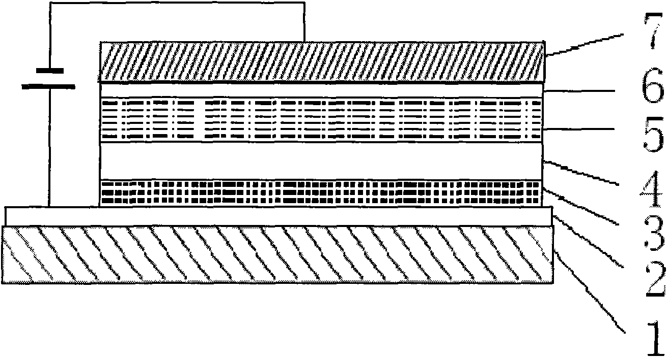
[0022] Such as figure 1 As shown, the organic electroluminescent display device provided by the present invention includes a glass substrate 1, and an ITO conductive layer 2, an anode interface modification layer 3, a hole transport layer 4, an electron Transport layer and luminescent layer 5, metal cathode Mg layer 6 and metal cathode layer 7, wherein, ITO conductive layer 2 and metal cathode Al layer 7 are respectively connected to the positive and negative electrodes of DC voltage, and the anode interface modification layer is doped with ZnO In the PEDOT:PSS layer of nanoparticles, the ZnO doped is 1%-10% of the mass of PEDOT:PSS.

[0023] The preparation of the ZnO-doped PEDOT:PSS anode interface modification layer solution is:

[0024] ZnO nanoparticles were added to a 5% PEDOT:PSS aqueous solution, and magnetically stirred at room...


PUM


Abstract

The invention discloses an organic electroluminescent display device, which comprises a glass substrate and an ITO conductive layer arranged on the upper surface of the glass substrate, wherein an anode interface modification layer, a hole transport layer, an electron transport layer, a luminescent layer, a metal cathode Mg layer and a metal cathode Al layer are sequentially arranged on the ITO conductive layer, and the anode interface modification layer is ZnO-doping PEDOT: PSS. The device takes the ZnO-doping PEDOT: PSS as the anode interface modification layer so as to reduce the hole injection barrier of a PEDOT: PSS layer and an ITO interface and improve the composite efficiency of holes and electrons, and meanwhile, the ZnO-doping PEDOT: PSS is also taken as a light scattering layer, so that crystal scattering can increase the luminous flux of the PEDOT: PSS layer, reduces the possibility that total-internal emission occurs among organic layers of a luminescent device, and improves the luminescent efficiency and brightness of organic OLED.

Description

technical field [0001] The invention belongs to the technical field of organic light-emitting display, and relates to an organic electroluminescent display device. Background technique [0002] OLED is driven by a certain electric field, electrons and holes are injected from the cathode and anode into the electron transport layer and the hole transport layer respectively, and meet in the light-emitting layer, the formed excitons finally lead to the emission of visible light. OLED requires high work function and good light transmittance for the anode material, so as to facilitate light exit from the device. The anode material is usually doped SnO 2 In 2 o 3 (In 2 o 3 :SnO 2 ), namely ITO. ITO should have a low sheet resistance and a flat surface to increase the light output of OLEDs and reduce the device operating voltage. ITO with a large surface roughness will affect the effective contact between ITO and the organic layer, as well as the effective injection of holes...

Claims


Application Information

Patent Timeline
Patent Type & Authority Applications(China)
IPC IPC(8): H01L51/50H01L51/52H01L51/54
Inventor 王香
Owner IRICO
Why Eureka
Try Eureka