Electro-hydraulic driver of control valve

A technology for controlling valves and actuators, applied to valve details, valve devices, engine components, etc., can solve problems such as response lag and slow dynamic response time, and achieve fast response speed, improved reliability, and large thrust or torque.

Inactive Publication Date: 2009-12-09
SHANDONG UNIV
View PDF0 Cites 37 Cited by
  • Summary
  • Abstract
  • Description
  • Claims
  • Application Information

AI Technical Summary

Problems solved by technology

[0004] The present invention aims at the problems of slow dynamic response time and response lag in the existing large-scale pressure regulating valves, and provides an elec

Method used


Image

  • Electro-hydraulic driver of control valve
  • Electro-hydraulic driver of control valve
  • Electro-hydraulic driver of control valve

Examples


Embodiment Construction

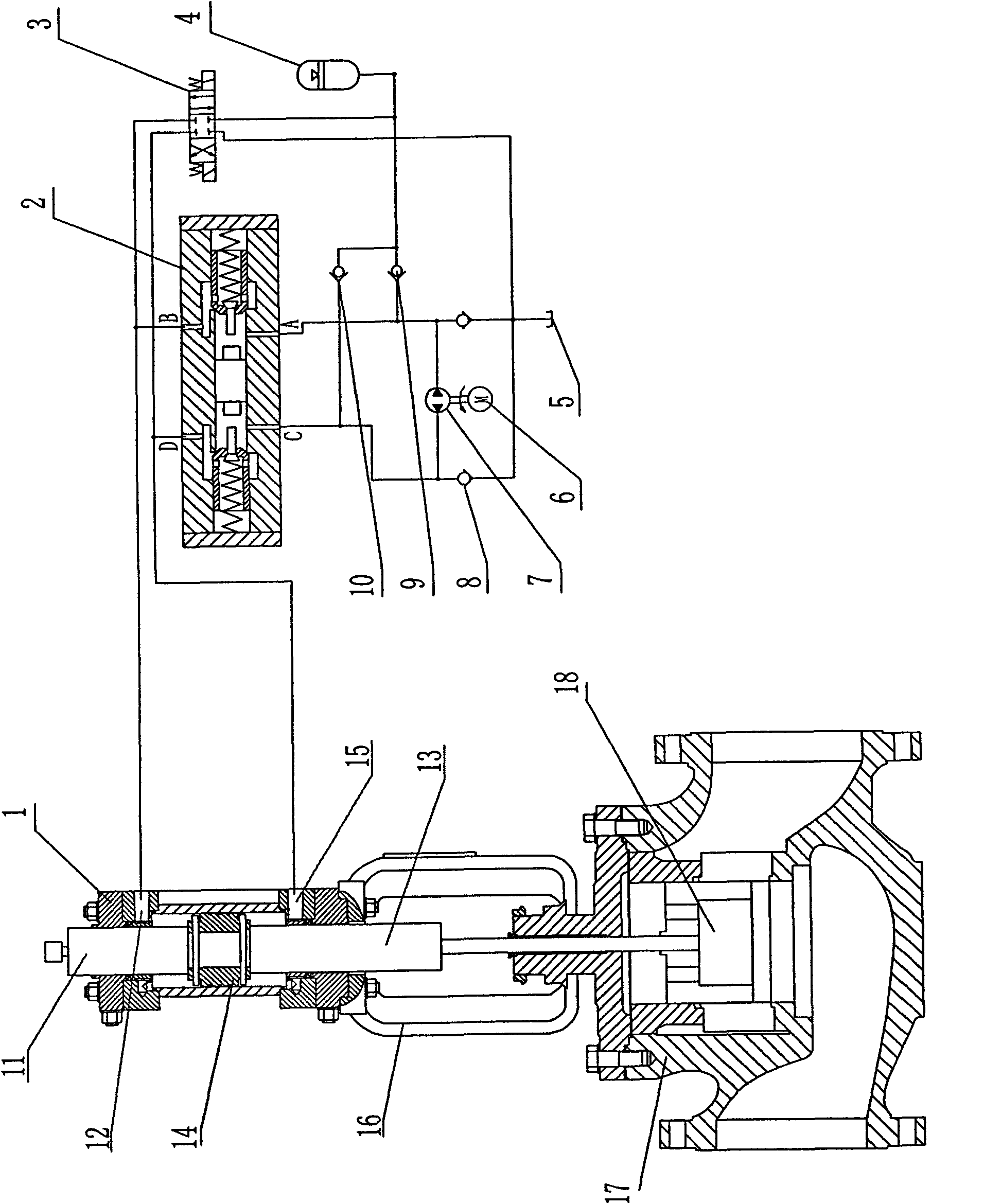
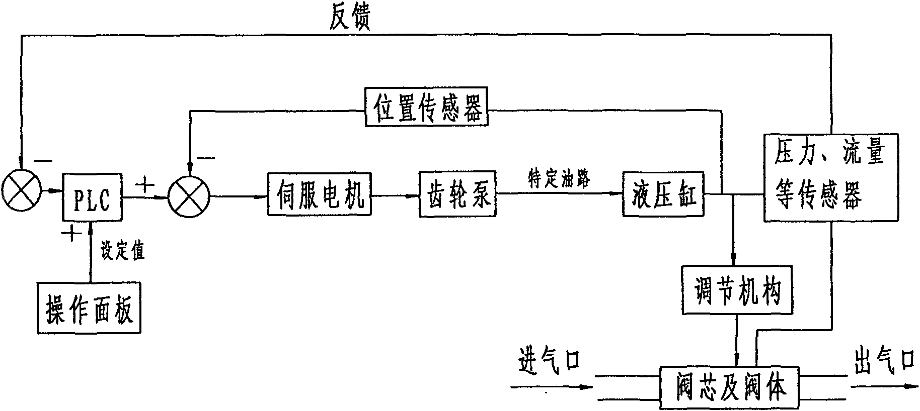
[0016] The control valve electro-hydraulic actuator of the present invention comprises a hydraulic drive system, a pressure sensor, a flow sensor, a position sensor and a control unit, and the hydraulic drive part, the pressure sensor, the flow sensor and the position sensor are all connected with the control unit (see figure 2 ).

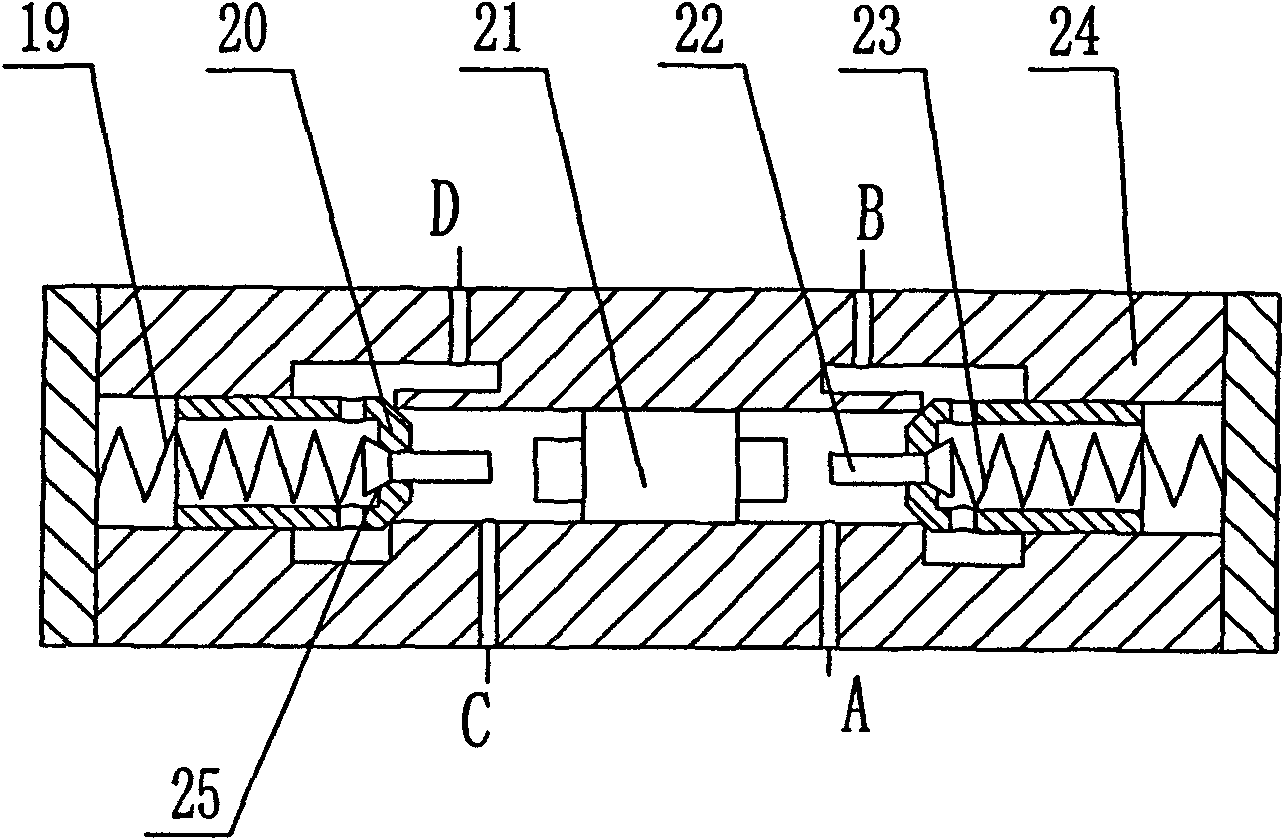
[0017] Such as figure 1 As shown, the hydraulic drive system mainly includes a double-acting drive cylinder 1, a directional control valve 2, a three-position four-way reversing valve 3, an accumulator 4, a servo motor 6, and a two-way gear pump 7, and the two-way gear pump 7 and the servo motor 6 connected, the operation is controlled by the servo motor 6, and the servo motor 6 is connected with the control unit (PLC). On the one hand, the oil inlet and the oil outlet of the bidirectional gear pump 7 are respectively connected to the accumulator 4 through the one-way valve 9 and the one-way valve 10, and the accumulator 4 is driven by the three-...


PUM


Abstract

The invention provides an electro-hydraulic driver of a control valve, which comprises a hydraulic driving system, a pressure sensor, a flow sensor, a position sensor and a control unit; wherein, the hydraulic driving system is used for driving a valve core of the control valve and comprises a bidirectional driving cylinder, a directional control valve, a three-position four-way reversing valve, an energy accumulator, a servo motor and a bidirectional gear pump; the pressure sensor and the flow sensor are installed on a fluid output pipeline, are used for detecting the pressure and the flow of the output fluid in the pipeline and are connected with the control unit; the position sensor is used for detecting the valve core position of the control valve to be controlled and is connected with the control unit. The electro-hydraulic driver realizes that hydraulic oil can flow out of an oil outlet cavity and directly enter an oil inlet cavity without passing through an oil tank, and has simple and compact structure; the motor and the oil pump do not need to continuously run but operate intermittently, which can not only save energy but also prolong the service life of the system, thus realizing stable operation for extra-long time and quick response of the control valve with high reliability.

Description

technical field [0001] The invention relates to an adjusting device for large flow fluid pressure control, which belongs to the technical field of control valves. Background technique [0002] The gas turbine generator set used in the cycle power generation project of the steel plant requires the input gas pressure to be stable. Due to technical, safety and cost reasons, gas pressure regulation is currently achieved using pneumatic pressure regulating valves. Large gas pressure fluctuations can cause severe surges. To prevent surge, pneumatic pressure regulating valves must be able to respond quickly, opening or closing quickly. The coke oven and blast furnace mixed gas supplied to each gas turbine is relatively large, up to tens of thousands of cubic meters per hour. Under such a large flow rate, it is very difficult to achieve pressure stability and quick response through ordinary large pneumatic pressure regulating valves, mainly due to slow dynamic response and hyster...

Claims


Application Information

Patent Timeline
IPC IPC(8): F16K31/124
Inventor 王勇刘延俊谢玉东
Owner SHANDONG UNIV
Why Eureka
Try Eureka