
Method and device for purifying the flue gases of a sintering process of ores and/or other material-containing materials in metal production

一种金属材料、金属的技术,应用在用于净化金属制备中由矿石和/或其他含金属材料的烧结工艺所产生的废气和装置领域,能够解决大设备花费等问题,达到简化方法、避免干扰、实施简单的效果

Active Publication Date: 2009-12-16
霍斯特·格罗霍夫斯基
View PDF4 Cites 20 Cited by
  • Summary
  • Abstract
  • Description
  • Claims
  • Application Information

AI Technical Summary

Problems solved by technology

[0008] What these known pre-cleaning steps have in common is that a great equipment outlay must be carried out for this and other consumable materials such as lime must be used and subsequently disposed of or further processed
Furthermore, in the case of wet scrubbing methods, corrosion issues, reheating issues and / or water handling issues must be overcome

Method used


Image

  • Method and device for purifying the flue gases of a sintering process of ores and/or other material-containing materials in metal production
  • Method and device for purifying the flue gases of a sintering process of ores and/or other material-containing materials in metal production
  • Method and device for purifying the flue gases of a sintering process of ores and/or other material-containing materials in metal production

Examples


no. 1 approach

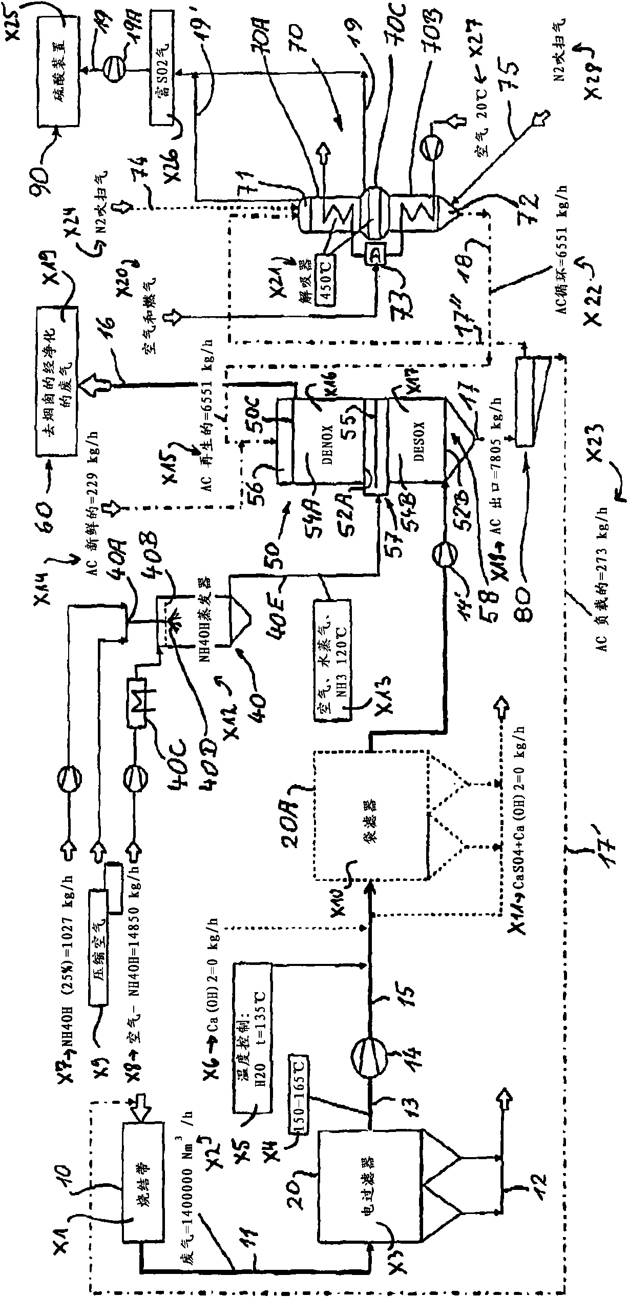
[0039] In the first embodiment using Figure 1A Operating conditions given in (without bag filter).

no. 2 approach

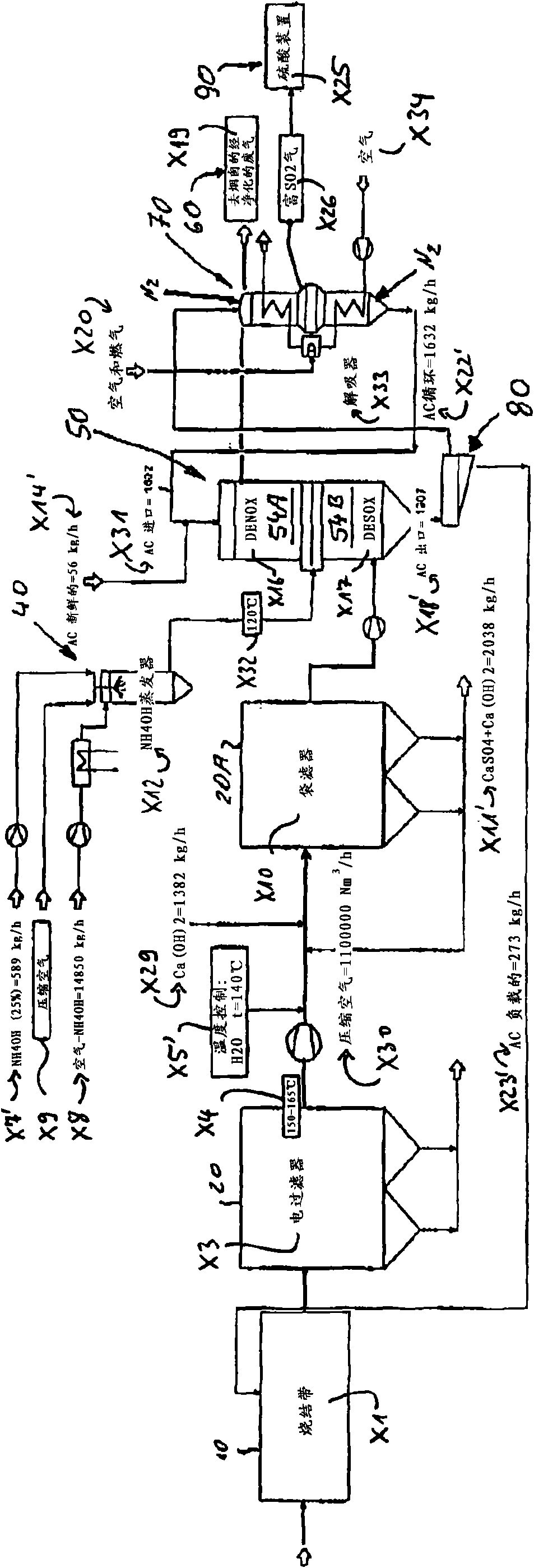
[0041] In the second embodiment using Figure 1B The operating conditions given in (when using a bag filter, the rest of the settings are the same as Figure 1A the same as in ).

[0042] exist Figure 1B In the embodiment, especially the consumption of activated coke, the amount of activated coke to be regenerated and the generated H 2 SO 4 significantly less than Figure 1A implementation plan.

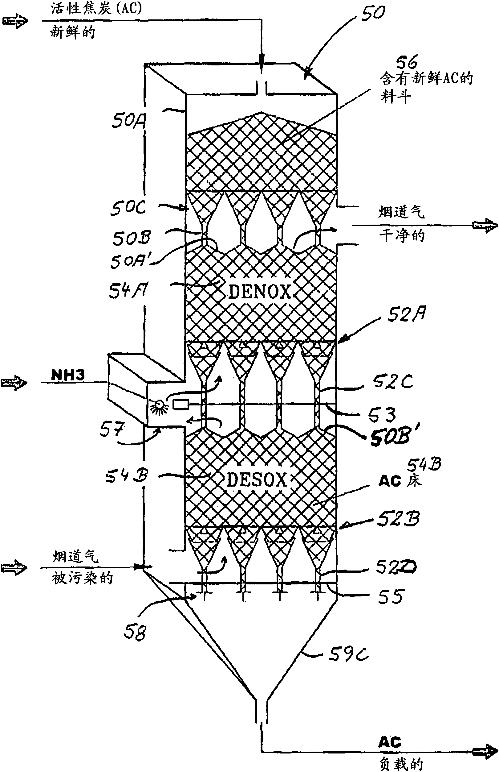
[0043] Depend on figure 2 It can be seen that the moving bed reactor 50 of the present invention in its simplest form consists of a vessel 50A of rectangular outline, at the upper end of which is replenished with activated coke in a storage hopper 56 located above. The activated coke is thus fed to the upper layer of activated coke 54A via the bulk material distribution pipes 50B arranged in a matrix form via the bulk material distribution plate 50C. This is done without a blocking unit or shut-off device so that pure gravity can be used for filling which ends automatically if...


PUM

PropertyMeasurementUnit
particle diameteraaaaaaaaaa

Abstract

The invention relates to a method for scrubbing effluent gases from a sintering process for ores in metal production, in which ore material is sintered with a solid fuel by combustion of the solid and passing through a carbonisation process, wherein at least the pollutants SOx and / or HCl and NOx are reduced or essentially removed. The sinter effluent gas is introduced into a moving bed reactor (50) from below through a lower and an upper layer (54B; 54A) of adsorption and / or absorption agent which is already charged with NOx and SOx and / or HCl, wherein at least the majority of the SOx and / or HCI components from the sinter effluent gas are absorbed in the pore system of the adsorption and / or absorption agent charged with NOx. The sinter effluent gas purified of the majority of the SOx and / or HCI components is homogeneously mixed with an ammoniacal compound such as ammonia or urea and admitted from below into the upper layer of adsorption and / or absorption agent already charged with NOx and small amounts of SOx and / or HCl from below through an upper horizontal gas influx and bulk material outlet floor (52A) of the moving bed reactor. On flowing through the upper layer (54A) at least the majority of NOx components from the sinter effluent gas is absorbed on the surface of the absorption / adsorption agent charged with NOx or N2 and small amounts of SOx and / or HCl. Fresh and / or regenerated adsorption / absorption agent is introduced via a bulk material distribution floor (50C) at the upper end of the moving bed reactor and continuously moves through the upper and lower layer of the whole moving bed reactor wherein firstly Nox and N2 and steam are absorbed on the surface thereof and then SOx and / or HCl are absorbed in the pore system thereof.

Description

technical field [0001] The invention relates to a method according to the preamble of claim 1 for purifying waste gases produced by the sintering process of ores during the production of metals and a device for carrying out the method according to the preamble of claim 11 . Background technique [0002] In the sintering of ore material, the material is mixed with solids containing small particles of carbon and placed on a sintering belt where the material is transported to the outlet with at least partial combustion of the solids during its forward transport on the sintering belt. Material end. Alternatively, the raw material is pelletized or briquetted and then sintered. Supply combustion air. During sintering, the feed material is subjected to a smoldering and at least partial combustion process whereby the raw material is agglomerated, ie sintered into larger pieces. Since the supplied combustion air increases the combustion and smoldering process, the feed releases a ...

Claims


Application Information

Patent Timeline
Patent Type & Authority Applications(China)
IPC IPC(8): B01D53/60B01D53/12B01J8/12
CPCB01D53/08B01D53/60B01D2258/025B01D2251/2062B01D2253/102B01D2257/2045B01D53/83B01D53/685Y02A50/20B01D53/12B01J8/12
Inventor 霍斯特·格罗霍夫斯基
Owner 霍斯特·格罗霍夫斯基
Learn More