Hot rolling oil for steel member and method for hot rolling steel member

A hot-rolled oil and steel technology, applied in the direction of rolls, metal rolling, metal rolling, etc., can solve the problems of poor load reduction effect, poor heat-proof adhesion or lubricity, unclear influence of cooling water, etc., to reduce rolling The effect of reducing the rolling load and reducing the rolling cost

Inactive Publication Date: 2009-12-16
KYODO YUSHI CO LTD
View PDF9 Cites 2 Cited by
  • Summary
  • Abstract
  • Description
  • Claims
  • Application Information

AI Technical Summary

Problems solved by technology

However, it is difficult for the waterproof plate to completely follow the high-speed rotating work roll, and a gap is formed between the waterproof plate and the work roll, and the roll cooling water flows into the surface of the work roll to form a water film, so that the adhesion of the rolling oil is deteriorated, and it cannot Achieve sufficient rolling load reduction effect
On the other hand, there is also a method of spraying hot rolling oil to the backup rolls, but compared with the case of supplying oil to the work rolls, the rolling oil adhering to the surface of the rolls passes through the surface of the work rolls to reach the rolls and the rolling material. Between, therefore, poor adhesion, less load reduction effect compared to work roll oiling
[0005] In order to solve this problem, a waterproof device for rolling mill rolls has been proposed (Patent Document 1), but it is not practical because the followability to high-speed rotating rolls is not clear, and the waterproof mechanism is complicated.
[0006] There is also a method of hot rolling a thick steel plate (patent document 2) characterized by supplying a lubricant containing an overbased metal sulfate to the surface of a roll (Patent Document 2), which contains an overbased metal sulfate, graphite, calcium carbonate and Lubricant plastics for rolling of sulfonate (Patent Document 3), hot rolling oil and hot rolling method mainly composed of palm oil (Patent Document 4), however, these lubricants are anti-stick Or the lubricity is poor, so the desired purpose cannot be achieved
[0007] On the other hand, there is a hot rolling method in which a lubricant is supplied to each of the work roll and the back-up roll during seamless rolling (Patent Document 5), and a method in which rolling oil is sprayed onto the surfaces of the upper and lower work rolls and the upper and lower back-up rolls. (Patent Document 6), but the influence of roller cooling water is not clear

Method used


Image

  • Hot rolling oil for steel member and method for hot rolling steel member
  • Hot rolling oil for steel member and method for hot rolling steel member
  • Hot rolling oil for steel member and method for hot rolling steel member

Examples


Embodiment

[0043] Hereinafter, the present invention will be specifically described based on examples.

[0044] Example

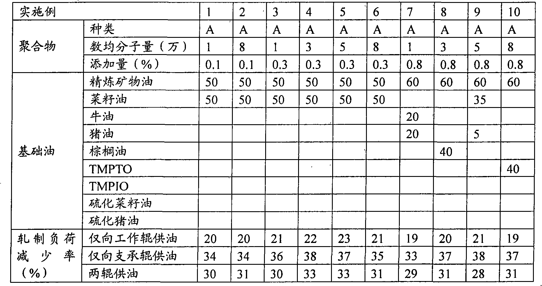
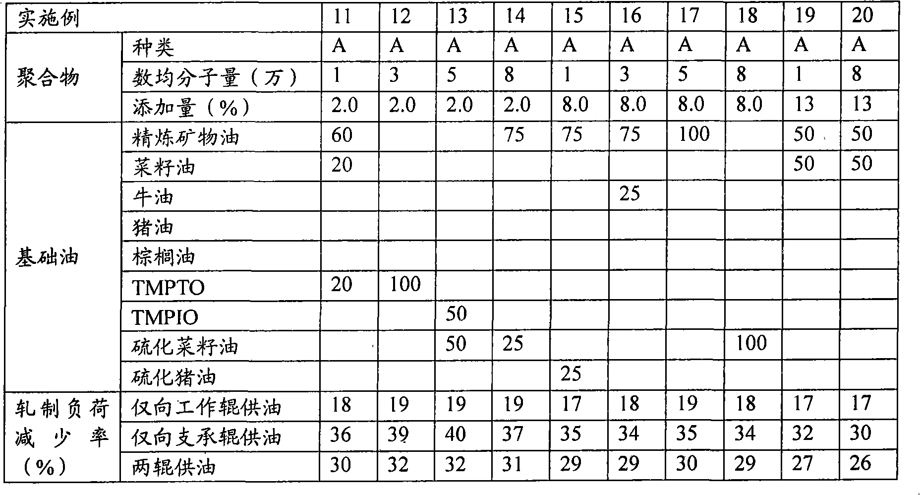
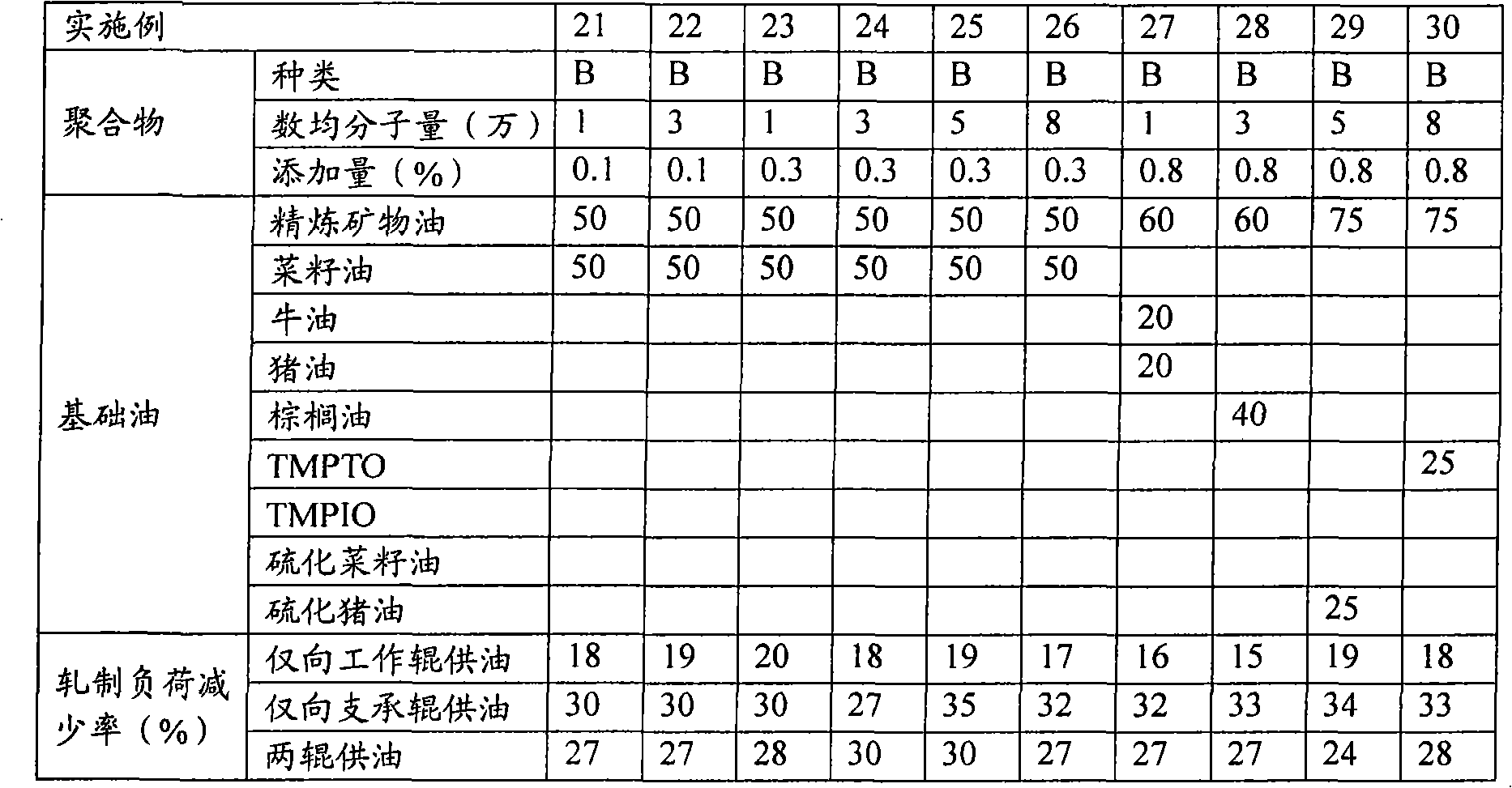
[0045] Using a four-stage hot rolling mill equipped with upper and lower backup rolls and upper and lower work rolls, according to the rolling conditions shown in Table 1, the rolling oil shown in Table 2 to Table 7 is supplied to the upper and lower backup rolls and / or the upper and lower rolls by water injection. work roll. The rolling load was measured with a rolling load meter installed in the rolling mill. Assuming that the rolling load when rolling oil is not supplied is X, and the rolling load when rolling oil is supplied is Y, the rolling load reduction rate (%) is obtained by the following formula.

[0046] Rolling load reduction rate (%)=100×(X-Y) / X

[0047] Table 1

[0048] work roll

High speed steel roller (diameter 80cm length 175cm)

backup roll

Forged roll (diameter 125cm length 175cm)

Fuel supply method

water injec...


PUM


Abstract

Disclosed is a hot rolling oil which enables to reduce a rolling cost by effectively decreasing a rolling load when a steel member is heated and rolled within a temperature range of 200-1200 DEG C. Also disclosed is a method for hot rolling a steel member by using such a hot rolling oil. Specifically disclosed is a hot rolling oil containing a base oil and at least one polymer selected from the group consisting of isobutylene homopolymers and isobutylene copolymers having a number average molecular weight of 8,000-100,000. Also specifically disclosed is a method for hot rolling a steel member, which is characterized in that the hot rolling oil is fed by a water injection system.

Description

technical field [0001] The invention relates to a hot-rolling oil for steel and a hot-rolling method for steel. In particular, it relates to a hot-rolling oil for steel and steel that can make the friction coefficient between the roll and the steel equal to or higher than that without oil supply and reduce the rolling load when the steel is heated at 200 to 1200°C for hot rolling. hot rolling method. Background technique [0002] In recent years, when steel materials such as carbon steel, stainless steel, tool steel, and silicon steel are subjected to medium-temperature rolling or hot rolling, high-temperature lubricants are used to obtain an effect in order to prevent the texture of the roll surface from being rough. As the lubricant, solid lubricants such as graphite, glass, boron nitride, mica, molybdenum disulfide, iron oxide, graphite fluoride, calcium carbonate, etc., sulfurized grease, sulfurized olefin, zinc dialkyldithiophosphate, Extreme pressure lubricants such ...

Claims


Application Information

Patent Timeline
Patent Type & Authority Applications(China)
IPC IPC(8): C10M143/06B21B27/10B21B29/00C10N20/04C10N30/00C10N40/24
CPCC10N2220/021C10M143/06C10N2240/404C10M2205/026C10N2020/04C10N2040/242
Inventor 伊原肇下斗米直
Owner KYODO YUSHI CO LTD
Why Eureka
Try Eureka