Closed-loop detection circuit of interferential full optical-fiber current mutual inductor

A current transformer and closed-loop detection technology, which is applied in the direction of measuring current/voltage, voltage/current isolation, instruments, etc., can solve the problems of reducing the accuracy of optical fiber current transformers, decreasing the accuracy of closed-loop control, and reducing the reliability of circuits, etc., to achieve improved Effects of stability and usability, improvement of reliability, and suppression of influence of detection accuracy

Inactive Publication Date: 2010-01-06
SHANGHAI XINYUE METER FACTORY
View PDF0 Cites 25 Cited by
  • Summary
  • Abstract
  • Description
  • Claims
  • Application Information

AI Technical Summary

Problems solved by technology

A set of optical fiber current transformer detection circuits that can be found now, its signal processing adopts the scheme of FPGA processor and DSP coprocessor. Due to the increase of components, it is necessary to increase a large number of solder joints and connections, which is The complexity of the circuit is greatly increased, which will inevitably reduce the reliability of the circuit; and the closed-loop control unit of the detection circuit generates the voltage control signal by first generating two analog signals and then combining them, which also increases a large number of external At the same time, signal distortion and deformation will inevitably occur during analog signal processing, which will directly lead to a decrease in the accuracy of closed-loop control, thereby reducing the accuracy of the optical fiber current transformer

Method used


Image

  • Closed-loop detection circuit of interferential full optical-fiber current mutual inductor
  • Closed-loop detection circuit of interferential full optical-fiber current mutual inductor
  • Closed-loop detection circuit of interferential full optical-fiber current mutual inductor

Examples


Embodiment

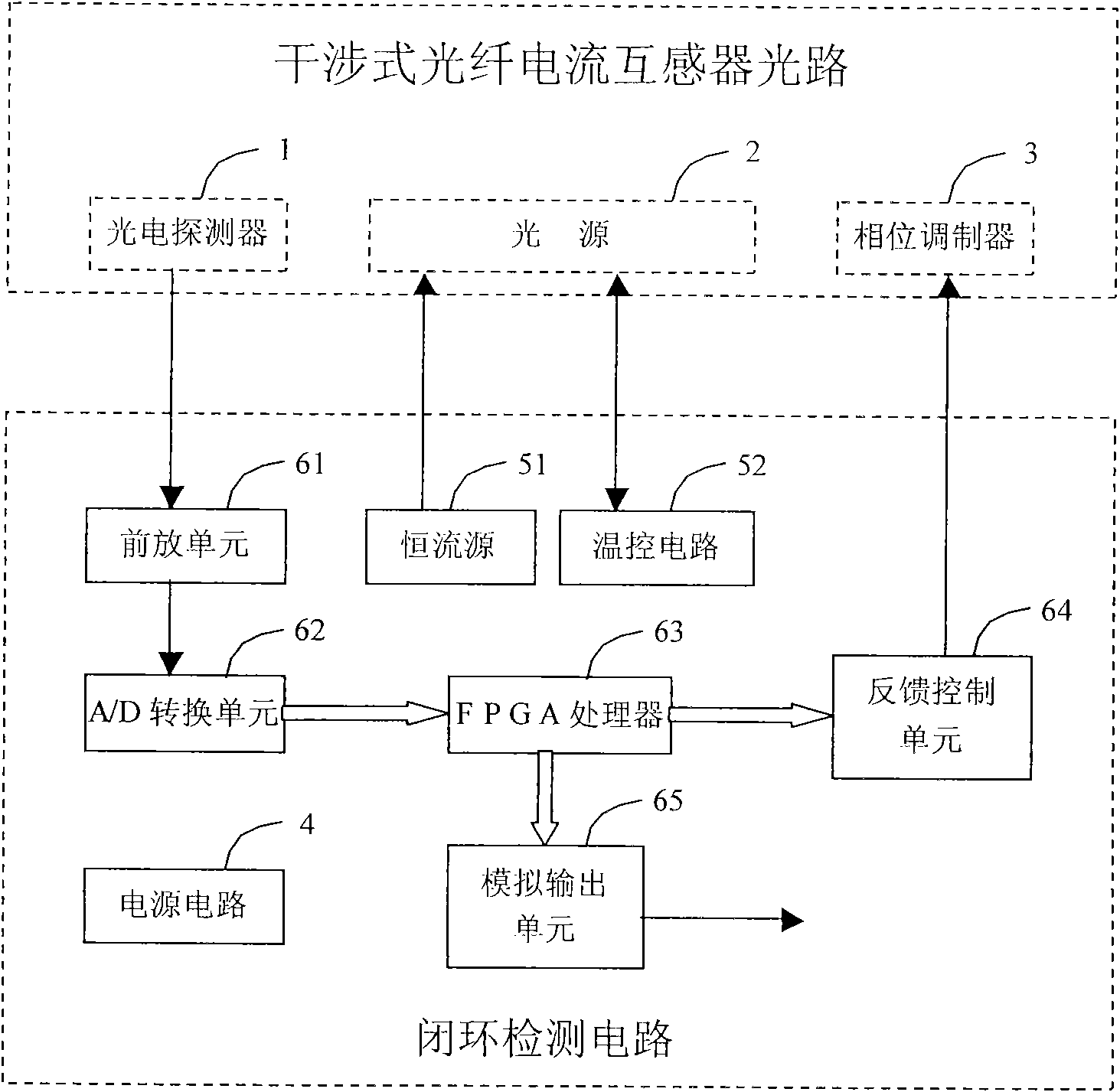
[0027] The basic working principle of fiber optic interference current transformer is the Faraday effect of light. The current generates a magnetic field around the conductor. Through a specially designed optical structure, the phase of the circularly polarized light traveling in the sensing fiber is affected by the current magnetic field, and the phase changes; and the magnitude of the phase shift is proportional to the magnitude of the current in the conductor. By measuring the magnitude of the phase shift between two coherent beams of light, the current value in the conductor can be measured.

[0028] (1) Electrical connection of the closed-loop detection circuit of the interferometric all-optical current transformer

[0029] see figure 1 As shown, the electrical connection of the interferometric all-optical fiber current transformer closed-loop detection circuit is as follows: the corresponding ports of the light source 2 are respectively connected to the output end of th...


PUM


Abstract

The invention discloses a closed-loop detection circuit of an interferential full optical-fiber current mutual inductor, which comprises a power supply circuit, an optical-source driving circuit, a signal processing circuit and a closed-loop detection circuit, wherein the closed-loop detection circuit aims at a ring-type optical-fiber optics interferential current mutual inductor and a reflecting interferential current mutual inductor and is based on FPGA. The gauge head of the optical-fiber current mutual inductor converts current intensity into optical-phase deviation. A front amplifier unit in a closed-loop detector receives an optical-intensity signal outputted by an optical-fiber detector, and after A/D conversion, the optical-intensity signal is outputted to the FPGA; the FPGA processes the received optical-intensity signal and decodes out a corresponding phase signal which generates a corresponding feedback-control signal by D/A, and the feedback-control signal is amplified by an operational amplifier and outputted to control a phase modulator; and an instant current value is obtained by internal operation, and converted into an analog voltage signal by a second path of D/A and outputted to a merging unit. The closed-loop detection circuit has the advantages of broad measuring frequency band, high measuring precision, wide dynamic range and the like, and is suitable for the electric transmitting and transforming trade and occasions of measuring heavy current.

Description

technical field [0001] The invention relates to a closed-loop detection circuit for a ring-type optical fiber optical interference current transformer and a reflection-type interference current transformer. The detection circuit adopts the principle of closed-loop feedback control to measure the phase change of light in the optical fiber current transformer, which can greatly reduce noise interference, weaken the influence of changes in environmental conditions such as temperature, improve measurement accuracy, and accurately measure the current value. Background technique [0002] As an important device in the power system, the current transformer plays an extremely important role in the process of electric energy metering and relay protection. Now the common traditional current transformer adopts the air-core coil structure based on the principle of electromagnetic induction. Its working principle itself leads to some difficult technical problems in actual use, such as: it...

Claims


Application Information

Patent Timeline
Patent Type & Authority Applications(China)
IPC IPC(8): G01R15/24G01R19/00
Inventor 康伟李佳程李荣翔刘会文张海燕陈殿印
Owner SHANGHAI XINYUE METER FACTORY
Why Eureka
Try Eureka