Milling cutter manufacturing method

A technology of milling cutters and tool holders, which is applied in the field of manufacturing milling cutters, can solve the problems of repeated use and inability to sharpen, and achieve the effects of reduced component manufacturing costs, high cutting capacity, and reduced machine tool investment requirements

Inactive Publication Date: 2010-01-06
ROLLS ROYCE PLC
View PDF4 Cites 24 Cited by
  • Summary
  • Abstract
  • Description
  • Claims
  • Application Information

AI Technical Summary

Problems solved by technology

While this creates an inherently weak tooth form (with a wedge angle of about 50°), it will have little effect in the deburring operation, however, these often thin beveled knives will not withstand the delicate machining required to achieve the required capacity and stability. Machining operations such as milling, especi

Method used


Image

  • Milling cutter manufacturing method
  • Milling cutter manufacturing method
  • Milling cutter manufacturing method

Examples


Embodiment Construction

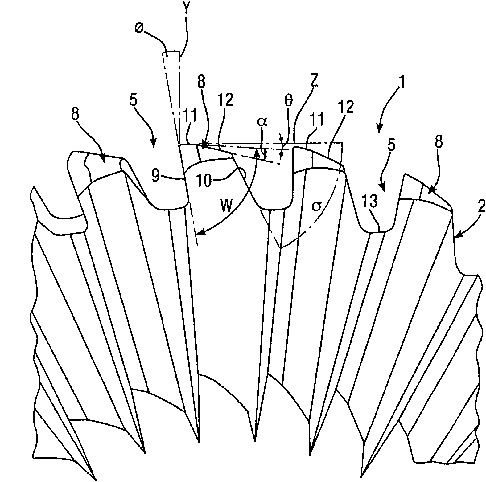
[0022] The finished milling cutter 1 according to the first embodiment is illustrated in Image 6 and 7 middle. The knife 1 has a cutting head 2 and a coaxial one-piece shank 3 intended to be fastened for rotation about an axis X in a chuck or tool holder of a machine tool.

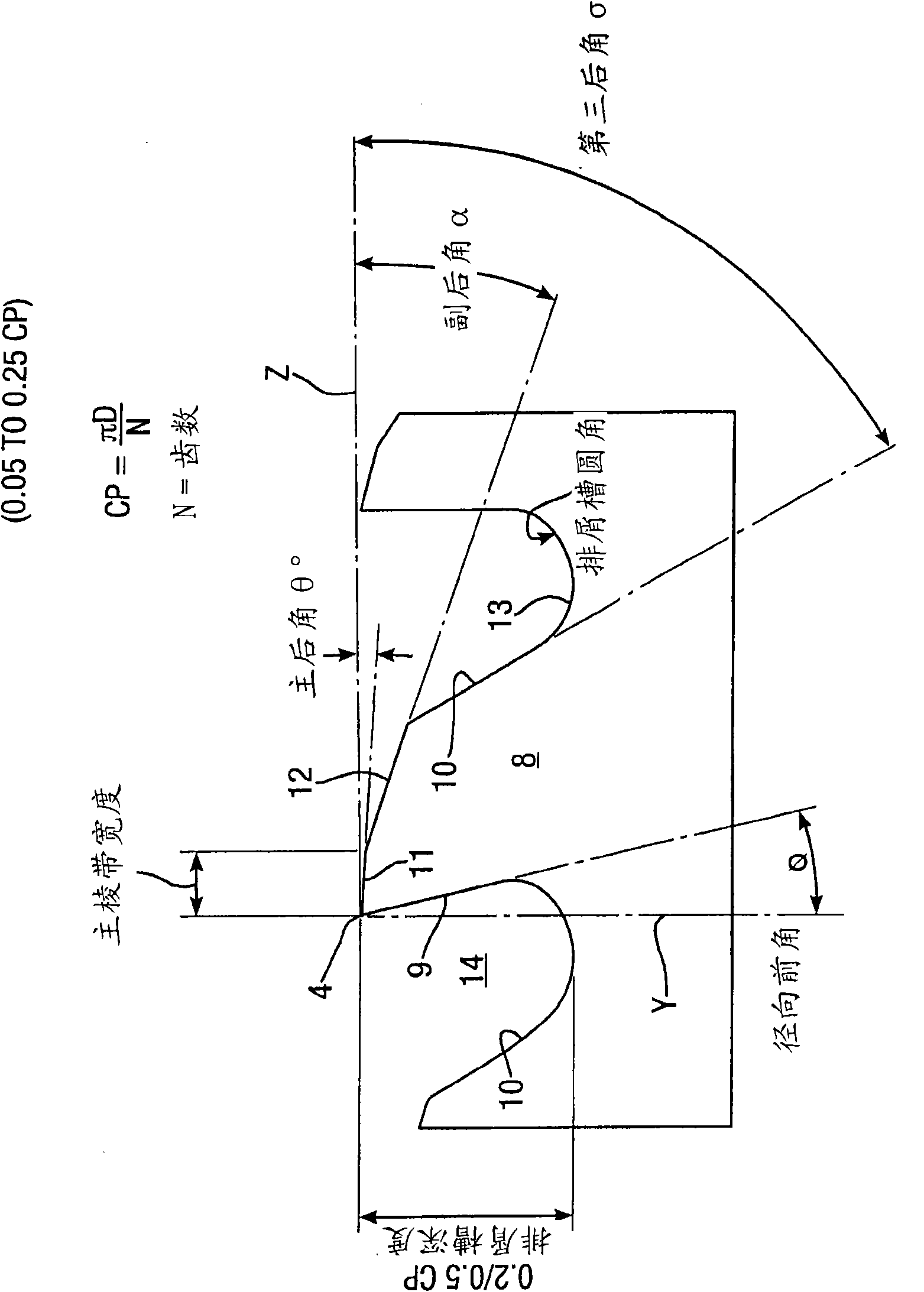
[0023] The cutting head 2 has a plurality (eg 30) of helical grooves 5 extending from a leading end 6 of the head 2 to a trailing end 7 of the head 2 . Each groove 5 has a tooth 8 comprising a guide face 9 and a back face 10, see figure 1 . The guide surface 9 faces the direction of rotation of the knife 1 in use and has the cutting tip 4 . The cutting tip 4 of each tooth 8 is located on the circumference of a pitch circle with a diameter D, see image 3 . The guide surface 9 has a positive radial rake angle radial rake angle is the angle formed by the inclined guide surface 9 and the radial line Y, see figure 2 , the radial line Y extends from the tool axis X to the tip 4 of the tooth 8 . In...


PUM


Abstract

A method of manufacturing a milling cutter having a cutting head and a coaxial integral shank comprising the steps of grinding, in a first grinding operation, a plurality of helical flutes (5) into the outer periphery of a cutter blank from a lead end (24) using a peripheral area (16) of a first grinding wheel (15) generally of frusto-conical profile and rotatable about an axis (18) generally transversely of the milling cutter axis (1), which peripheral area (16) produces, simultaneously, the following three features: a leading face (9) of a trailing tooth; a rear face (10) on an adjacent preceding tooth; and a swarf removal gullet (13) having divergent sides, grinding, in a second grinding operation, and using a peripheral edge (19) of a second grinding wheel (20), a relief face (11), which extends rearwardly from a leading end of a tooth tip, resulting in a minimum tooth wedge angle of approximately 60 DEG, and grinding, in a third grinding operation, a radius (23) on the end of each flute. The invention also includes a milling cutter (1).

Description

technical field [0001] The present invention relates to a method for the manufacture of milling cutters for milling so-called special materials such as titanium alloys, stainless steel, Nimonico, etc., which are notoriously difficult to machine, and also to milling the knife itself. Background technique [0002] The aerospace industry uses titanium alloys and the like extensively and, like other industries, has been trying to reduce costs through more affordable outsourcing or higher productivity. [0003] Materials such as titanium, stainless steel, and Nimonico are non-mainstream in milling capabilities and challenge the capabilities of existing technologies to increase productivity. Although grinding processes have been developed that significantly increase productivity (even for specialty materials), there are still inevitably features in some parts that cannot be achieved by grinding wheels and thus cannot be formed by grinding, and these features have to be Realized ...

Claims


Application Information

Patent Timeline
IPC IPC(8): B24B3/06B24B19/04B23P15/34B23C5/10
CPCB23C5/10B24B19/04B24B3/065Y10T407/1946Y10T82/10Y10T407/1958B23P15/24
Inventor M·柯比C·P·R·希尔
Owner ROLLS ROYCE PLC
Why Eureka
Try Eureka