

Large area MEMS membrane type gas enricher
A large-area, enricher technology, applied to semiconductor/solid-state device components, instruments, scientific instruments, etc., can solve the problems of mechanical strength that is difficult to support suspended structures, small enrichment area, and unfavorable large airflow.
- Summary
- Abstract
- Description
- Claims
- Application Information
AI Technical Summary
Problems solved by technology
Method used
Image

Examples
Embodiment 1
[0025] Example 1 - Straight
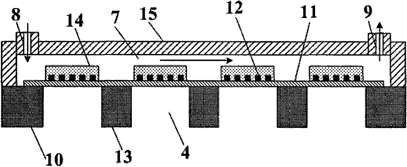
[0026] figure 2 It is a schematic diagram of the structure of a large-area enrichment device in which the enrichment units are arranged in a straight line. It contains a total of 4 enrichment units. Of course, it can also be composed of more enrichment units. The main structure includes a silicon frame 10 , a SiN diaphragm (a suspended diaphragm 11 ), a heating element 12 , a silicon frame 13 , a selective adsorption film 14 , and a glass top cover 15 . Typically, about 500 μm thick silicon is used as the substrate. A SiN film layer (suspended diaphragm 11 ) of about 1 μm is prepared on the front surface of the substrate by plasma enhanced chemical vapor deposition (PECVD), and a silicon dioxide film can also be used. Then, four serpentine heating elements 12 were manufactured according to the design of the linear combination. The heating material is a platinum thin film with a film thickness of about 200nm and a size of 1.8mm×1.8mm. It is dep...
Embodiment 2
[0028] Example 2 - Parallel type
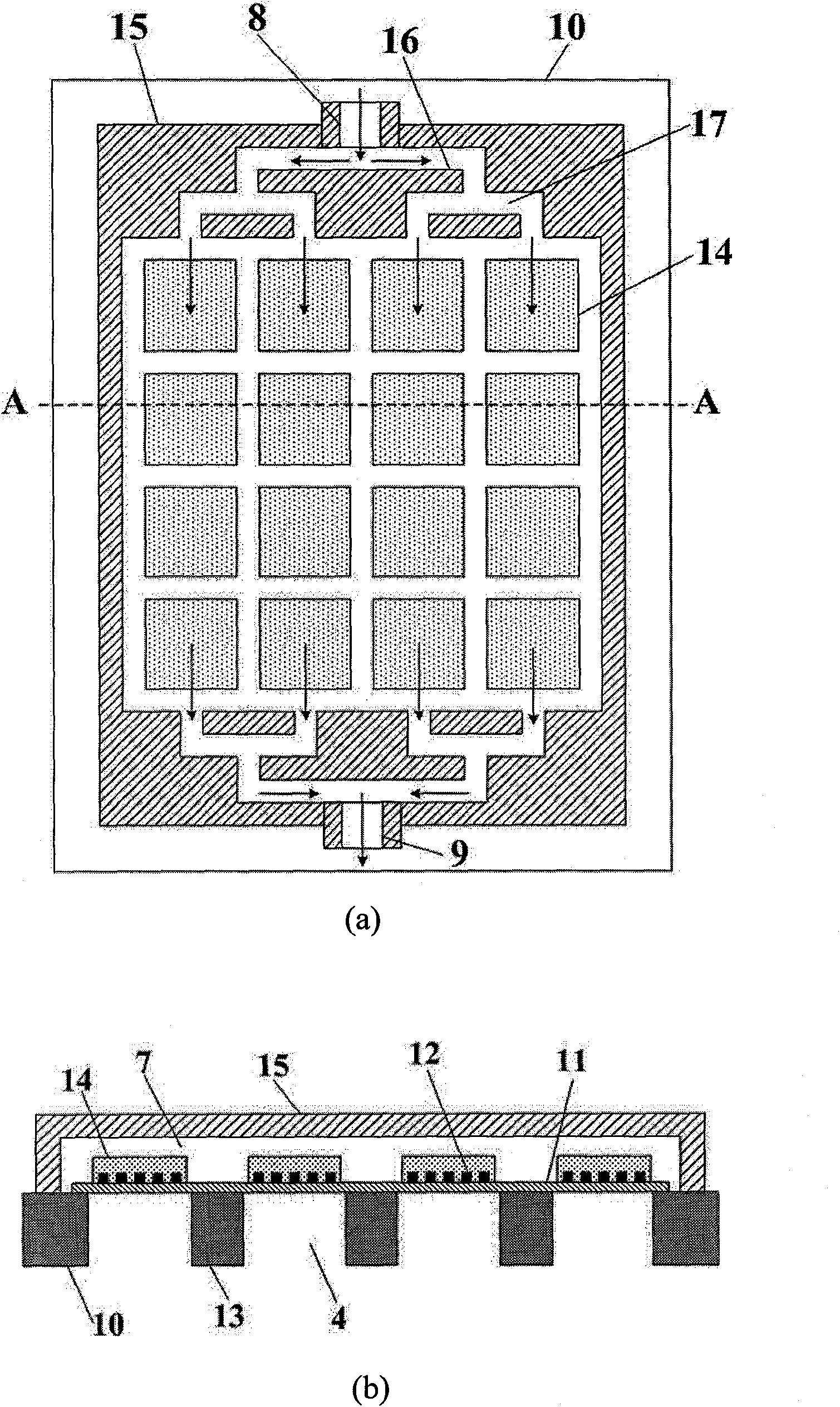
[0029] image 3 It is a schematic diagram of the structure of a large-area concentrator composed of 16 enrichment units, which is equivalent to arranging 4 columns of linear concentrators together, with 4 enrichment units in each column. In order to make the air flow in each column uniform, gas distribution channels 17 are respectively designed at the air inlet 8 and the air outlet 9, so that the gas path is divided into two, and then divided into four, and the distance of each gas path is guaranteed to be equal, so that The 16 enrichment units can be evenly contacted with the gas, ensuring that each enrichment unit has the same adsorption function. The side-by-side combination method has a larger adsorption area than the linear type, and its enrichment rate for DMMP can reach 240.
Embodiment 3
[0030] Example 3 - Coil Type 1
[0031] Figure 4 It is a schematic diagram of the structure of a large-area concentrator with 16 enrichment units arranged in a coiled pattern. It is characterized in that a glass grid 16 is etched on the glass top cover 15, so that when the glass top cover 15 and the silicon substrate are bonded together , These glass grids 16 form a fixed gas path inside the enricher, so that the gas passes through the 16 enricher units sequentially along the winding gas path. The width of the glass grid 16 is about 0.5mm, the distance between the grids and the edge of the grid and the top cover is 3mm, the adsorption unit is in the middle position between the two grids, and the distance between the two adsorption units in the same row The distance is 0.5mm.
PUM
 Abstract
Description
Claims
Application Information