Device and method for mechanically controlling exposure time

A technology of exposure time and mechanical control, which is applied to control exposure, optics, cameras, etc., can solve problems such as motor speed control, and achieve the effects of large dynamic range, good uniformity, reliability, and high precision

Inactive Publication Date: 2010-01-27
NAT SPACE SCI CENT CAS
View PDF0 Cites 8 Cited by
  • Summary
  • Abstract
  • Description
  • Claims
  • Application Information

AI Technical Summary

Problems solved by technology

However, compared with the method of controlling the motor, the low-end exposure time points that can be realized by the grid method are relatively small, and different low-end

Method used


Image

  • Device and method for mechanically controlling exposure time
  • Device and method for mechanically controlling exposure time

Examples


Embodiment 1

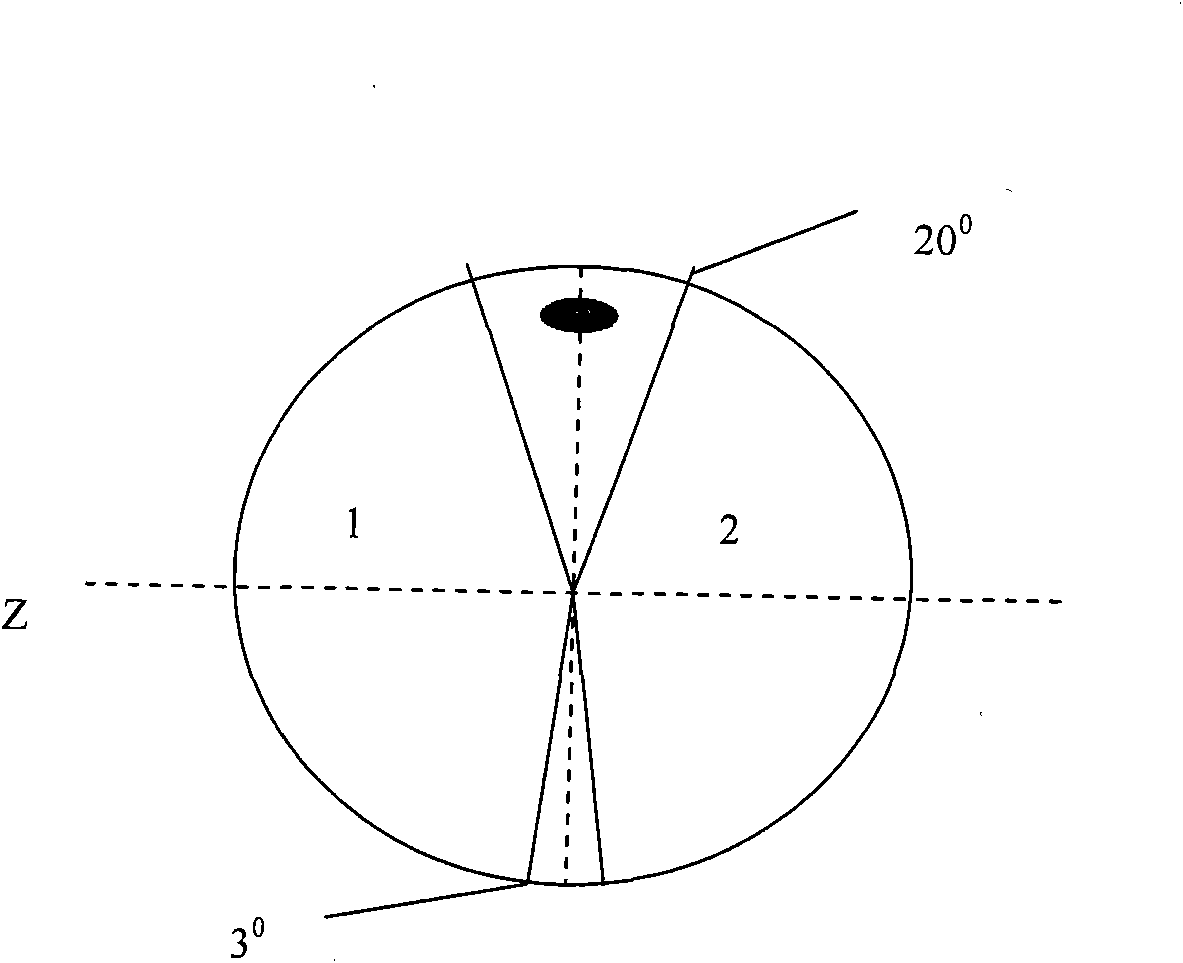
[0027] A schematic diagram of the exposure control aluminum plate of the SXIT telescope is attached figure 2 , the solid dot in the figure represents the light source that is located on the center line of the 20-degree aperture of the shutter. From an engineering point of view, the light source can be considered to be stationary. There are two fan-shaped holes of different sizes on the shutter, and the degree of the opening can be formulated according to actual needs, such as 2-5 degrees for the small hole, 20-30 degrees for the large hole, etc. In this embodiment, the degree of the shutter opening is 3 degrees and 20 degrees, and the rest are shielded areas. Taking the openings of 3 degrees and 20 degrees as examples, how the device realizes the control of different exposure times is explained from the control mode. Let 3 degrees and 20 degrees be S and L holes respectively. attached figure 2 It is stipulated that the Z axis is perpendicular to the center line of the S a...


PUM


Abstract

The invention provides a device for mechanically controlling exposure time, which comprises a disc-like shutter with a fan-shaped hole, a direct current brushless motor for controlling the rotation of the disc-like shutter, and a control circuit for controlling the rotational speed of the direct current brushless motor, wherein the control circuit is used for computing the rotational speed of the direct current brushless motor according to the currently-required exposure time and the current position of the disc-like shutter, and controlling the direct current brushless motor to work at the rotational speed. The invention simultaneously provides a corresponding method for controlling the exposure time. The device and the method utilize a speed modulation and large-hole residing mode to realize the exposure time, and can realize 27 segments of exposure time, wherein the minimum accurate exposure time can reach 2 ms and the maximum accurate exposure time can be infinitely extended upwards, thus the dynamic range is wide; the consistency, the uniformity and the reliability are all good; the accuracy is high; and the device and the method can be applied to aerospace systems and ground systems.

Description

technical field [0001] The invention belongs to the technical field of space astronomical observation, in particular, the invention relates to an exposure time control device and a control method of an imaging observation instrument. Background technique [0002] Exposure time control device is a key component in imaging instruments for astronomical observation. For some imaging instruments, such as imaging instruments in the solar X-ray band, the exposure time control device needs to be greater than 10 4 Order of magnitude dynamic range for clear images of the sun in different conditions. Exposure time control devices for space applications need to meet space operation requirements such as radiation resistance, high uniformity, long life, and high reliability, so common exposure time control devices cannot meet the requirements for use. Brushless DC motor has many advantages such as uniform speed, fast steering, long life, good positioning ability, etc. It is widely used ...

Claims


Application Information

Patent Timeline
IPC IPC(8): G03B7/083G03B9/08G02B23/00
Inventor 李保权朱光武张鑫彭吉龙刘杰冬雷曾智蓉
Owner NAT SPACE SCI CENT CAS
Why Eureka
Try Eureka