
Method and device for spraying silicic acid produced from oriented silicon steel having good bottom layer

A technology of oriented silicon steel and bottom layer, applied in the field of silicic acid spraying method and device, can solve the problems of reduced production efficiency, powder oxidation, affecting the formation of magnesium silicate bottom layer, etc., and achieves the effect of improving insulation performance

Active Publication Date: 2010-02-03
BAOSHAN IRON & STEEL CO LTD
View PDF3 Cites 4 Cited by
  • Summary
  • Abstract
  • Description
  • Claims
  • Application Information

AI Technical Summary

Problems solved by technology

[0014] If the arc power is too low, part of the ionized gas and a lower temperature plasma flame will be obtained, which will cause insufficient heating of the particles, and the coating will have lower bonding strength, hardness and deposition efficiency.
[0015]③ Powder supply: The powder supply speed must be compatible with the input power. If it is too large, raw powder (unmelted) will appear, resulting in a decrease in spraying efficiency; if it is too low, the powder Severe oxidation and overheating of the substrate
Otherwise, it may lead to the failure of this process. Under the strict requirements of temperature, dew point and atmosphere, if the equipment fluctuates slightly, it will lead to the inability to form uniform and dense SiO on the surface of the steel plate. 2 film, thereby affecting the formation of the magnesium silicate bottom layer;
[0023] Second, in order to ensure the formation of a good magnesium silicate bottom layer, there are strict requirements on the particle size, hydration rate, and impurity elements of MgO, and the baking temperature and time of MgO are also strictly controlled. If these conditions cannot Meeting the standard requirements will affect the formation of the bottom layer of magnesium silicate;
[0024] Third, a long time (about 10 hours or more) low heat preservation annealing is required in the high temperature annealing stage to eliminate the crystal water in MgO, so the production efficiency is reduced;
[0025] Fourth, in the high-temperature annealing stage, it is necessary to strictly control the heating rate in order to provide sufficient conditions for the formation of the magnesium silicate bottom layer, which will also lead to a reduction in production efficiency;
[0026] Fifth, in the high-temperature annealing stage, due to the thick magnesium oxide coating and low thermal conductivity, the temperature difference between the cold and hot spots of the steel coil is large, so the temperature rise of the steel coil must be reduced speed, which will also lead to a reduction in production efficiency
[0027] It can be seen from the above that the formation process of the bottom layer is relatively long at present, and there are many control factors related to the quality of the bottom layer with significant influence. class defects, and even the phenomenon of dew crystals at the bottom
Serious bottom dew crystals will cause damage to grain-oriented silicon steel during use, resulting in huge economic losses

Method used


Image

  • Method and device for spraying silicic acid produced from oriented silicon steel having good bottom layer

Examples


Embodiment 1

[0074] Produce grain-oriented silicon steel with the composition in the following table, and the composition is shown in Table 1:

[0075] Table 1

[0076]

[0077] A slab of the above composition was heated to 1180°C for 180 minutes. Then directly hot rolled to 2.3mm. The hot-rolled steel strip is annealed in two steps, first heated to 1130°C, and then lowered to 900°C in 200 seconds during the cooling process. The steel plate is subsequently quenched. After pickling, the steel strip is subjected to 5 passes of cold rolling, in which the 3rd and 4th passes are carried out at 220°C, and the thickness is reduced to 0.285mm. The cold-rolled steel strip is decarburized and annealed at 850°C for 200 seconds, and then nitriding is carried out at 700°C for 200 seconds. According to the following two processes for processing:

[0078] After decarburization annealing, plasma spray magnesium silicate on steel strip according to the following parameters: plasma gas flow r...

Embodiment 2

[0086] After the steel strip with the above composition is processed to decarburization by the process in Example 1, different plasma spraying magnesium silicate processes are adopted, wherein:

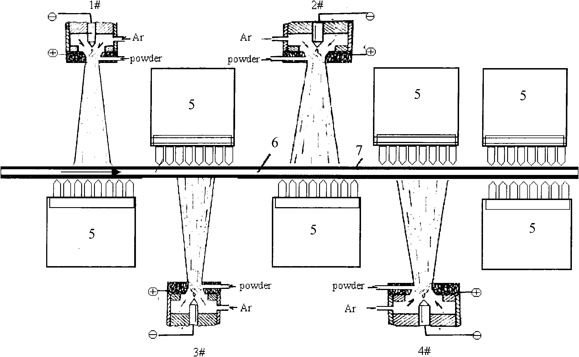
[0087] 1. The gas flow rate is 14L / min, the distance between 1# and 3# plasma sources is 100mm, the distance between 2# and 4# plasma sources is 100mm, and the spraying time is 200S;

[0088] 2. The gas flow rate is 16L / min, the distance between 1# and 3# is 100mm, the distance between 2# and 4# is 100mm, and the spraying time is 200S;

[0089] 3. The gas flow rate is 20L / min, the distance between 1# and 3# is 100mm, the distance between 2# and 4# is 100mm, and the spraying time is 200S;

[0090] 4. The gas flow rate is 20L / min, the distance between 1# and 3# is 150mm, the distance between 2# and 4# is 100mm, and the spraying time is 200S;

[0091] 5. The gas flow rate is 20L / min, the distance between 1# and 3# is 150mm, the distance between 2# and 4# is 100mm, and the spraying time ...


PUM


Abstract

The invention relates to a method for spraying magnesium silicate produced from oriented silicon steel having a good bottom layer, which comprises the following steps: putting oriented silicon steel strip steel after rolling and decarburizing annealing into a plasma spraying magnesium silicate chamber to perform plasma spraying magnesium silicate treatment; setting at least four plasma emission sources (1, 2, 3 and 4) in an up-down staggering mode on the strip steel in the plasma spraying magnesium silicate chamber; and setting gas injection cooling devices on the other side of the strip steelopposite to each plasma emission source, wherein the distance from the plasma emission sources to the strip steel is between 100 and 200 meters, the spraying time is between 200 and 300 seconds, andthe plasma Ar gas flow is between 14 and 20 liters per minute. The magnesium silicate bottom layer in the method has evener forming effect and excellent adhesive property; and the production process steps are simplified and the process stability is greatly improved.

Description

technical field [0001] The invention relates to the production technology of oriented silicon steel, in particular to a silicic acid spraying method and device for the production of oriented silicon steel with a good bottom layer. Background technique [0002] Oriented silicon steel is an iron-silicon alloy with a silicon content of about 3% and other components mainly iron. It is an indispensable and important soft magnetic alloy for electric power, electronics and military industries. It is mainly used as the iron core of transformers. Because of its complex production process and strict manufacturing technology, it is called the "handicraft" of today's global steel industry. [0003] The difference between grain-oriented silicon steel and other steel types is mainly three aspects: [0004] 1) It has a Gaussian texture, that is, (110)[001] texture, which has the best magnetic properties in the rolling direction of the silicon steel plate. The Goss texture of grain-orient...

Claims


Application Information

Patent Timeline
IPC IPC(8): C23C4/16C23C4/10C23C4/04C23C4/134
Inventor 胡卓超杨勇杰李国保吴培文
Owner BAOSHAN IRON & STEEL CO LTD
Learn More