Vibration monitoring structure and method based on optical fiber polarized light time domain reflection sense

A time-domain reflection and vibration monitoring technology, applied in measurement devices, using wave/particle radiation, measuring ultrasonic/sonic/infrasonic waves, etc., can solve the problems of reduced detection accuracy, slow response speed, long measurement period, etc., to achieve durability. Good, small amount of data calculation, the effect of reducing detection time and cost

Inactive Publication Date: 2010-02-03
NANJING UNIV
View PDF0 Cites 41 Cited by
  • Summary
  • Abstract
  • Description
  • Claims
  • Application Information

AI Technical Summary

Problems solved by technology

[0008] The currently used POTDR system uses a single-channel analyzer to detect the projection value of polarized light in a single direction in the detection of the polarization state. When the angle between the polarization direction of the signal light and the projection direction is close to 90 degrees, the projection power will be It will become very small, which will reduce the detection accuracy. Generally, this situation is called entering the dead zone state.
At the same time, the current POTDR system mainly relies on recursive calculations for the detection of the polarization state of scattered light. The algorithm is complex, the measurement period is long, and the response speed is slow.

Method used


Image

  • Vibration monitoring structure and method based on optical fiber polarized light time domain reflection sense
  • Vibration monitoring structure and method based on optical fiber polarized light time domain reflection sense

Examples


Embodiment Construction

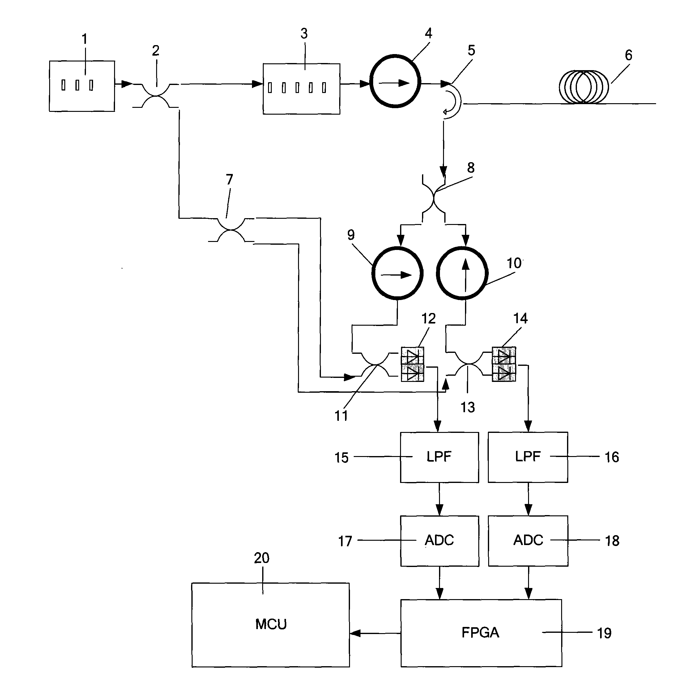
[0034] A POTDR-based detection structure for vibration frequency and intensity includes an optical sending module, an optical receiving module, a detection fiber, a control unit, and a signal processing unit; the optical sending module includes a laser for emitting a constant power laser, An acousto-optic modulator for pulse modulation of laser light, a polarization controller for polarizing laser light; the light receiving module includes an analyzer for detecting the polarization state of laser light, and a polarizer for converting optical signals into electrical A balanced detector for coherent detection of signals, a low-pass filter for removing interference, and an analog-to-digital converter for converting analog electrical signal samples into digital signals; the detection fiber includes a circulator for controlling the direction of laser light and a sensing optical fiber for vibration monitoring and sensing; the signal processing unit is used to receive the digital sign...


PUM


Abstract

The invention relates to a vibration monitoring structure based on optical fiber polarized light time domain reflection sense, comprising a laser (1), a first coupler (2), a second coupler (7), a third coupler (8), a fourth coupler (11), a fifth coupler (13), an acoustic optical modulator (3), a polarizer (4), a circulator (5), a sensing optical fiber (6), a first analyzer (9), a second analyzer (10), a first detector (12), a second detector (14), a first low-pass filter (15), a second low-pass filter (16), a first analog-to-digital converter (17), a second analog-to-digital converter (18), anFPGA (19) and a microprocessor MCU (20); the method comprises the following steps: measuring the changes of the polarization state of each optical fiber section with time according to a plurality ofmeasurements, combining Fourier transformation technology to obtain frequency spectrum information, and analyzing the frequency spectrum information to obtain vibration information. Compared with theprevious method which is adopted by a POTDR system and carries out iteration operation on polarization state, the method has the advantages of simple algorithm and small data operation and greatly reduces monitoring time and cost of the system.

Description

technical field [0001] The invention relates to a sensing device and method for vibration frequency and intensity monitoring, in particular to a vibration monitoring special device and a vibration monitoring method with distributed measurement based on optical fiber polarized light time domain reflection sensing. Background technique [0002] In the health monitoring of bridges and pipelines, many potential dangers are often manifested in some form of mechanical vibration. For example, the shaking of bridges, the movement of construction machinery around pipelines, etc. If the vibration can be monitored online, early warning of potential danger can be realized. [0003] Traditional vibration sensors mainly use the magnetoelectric effect and piezoelectric effect to convert vibration signals into electrical signals for measurement. This measurement method mainly has the following shortcomings: [0004] First of all, this measurement method can only support quasi-distributed...

Claims


Application Information

Patent Timeline
Patent Type & Authority Applications(China)
IPC IPC(8): G01H9/00
Inventor 王顺张旭苹张益昕谢飞
Owner NANJING UNIV
Why Eureka
Try Eureka