Laser double-faced synchronous machining system and machining method thereof
A simultaneous processing and laser technology, applied in laser welding equipment, metal processing equipment, manufacturing tools, etc., can solve the problems of insufficient repeat positioning accuracy of the workbench, excessive damage to the processing part, and misalignment of double-sided cutting, so as to improve the cutting quality and cutting efficiency, improving processing efficiency and processing quality, and the effect of narrow kerf
- Summary
- Abstract
- Description
- Claims
- Application Information
AI Technical Summary
Problems solved by technology
Method used
Image
Examples
Embodiment 1
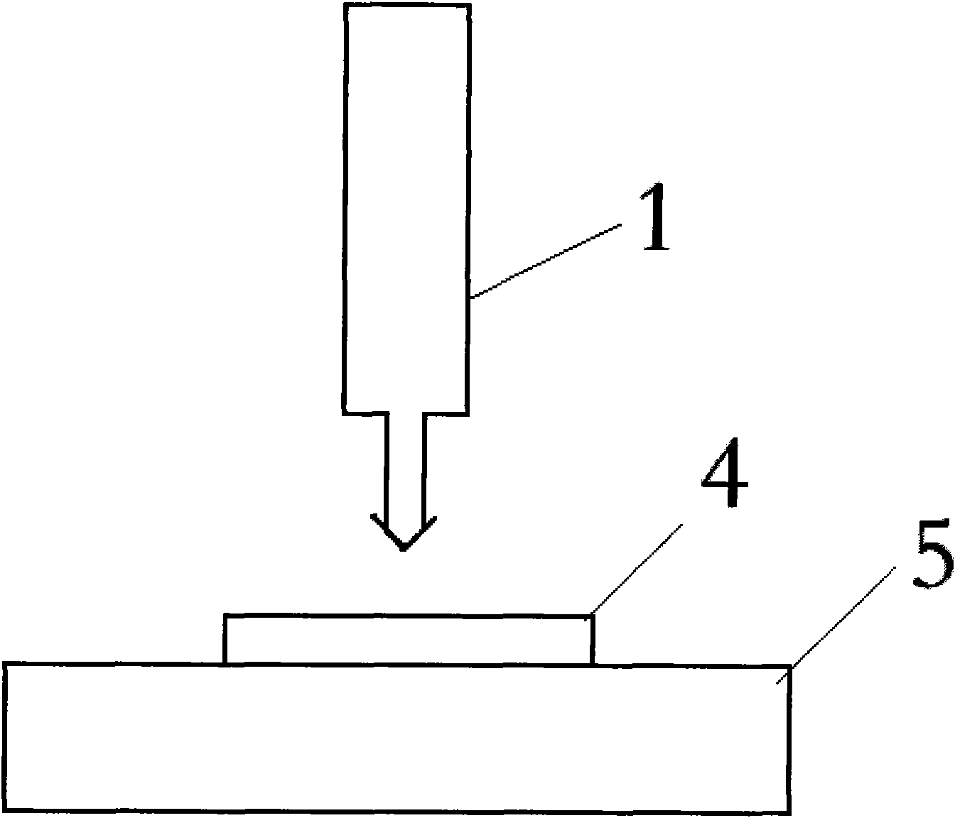
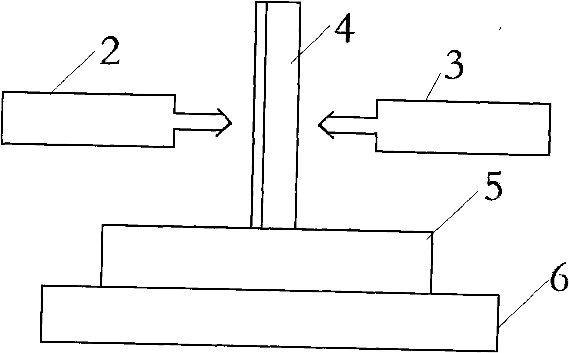
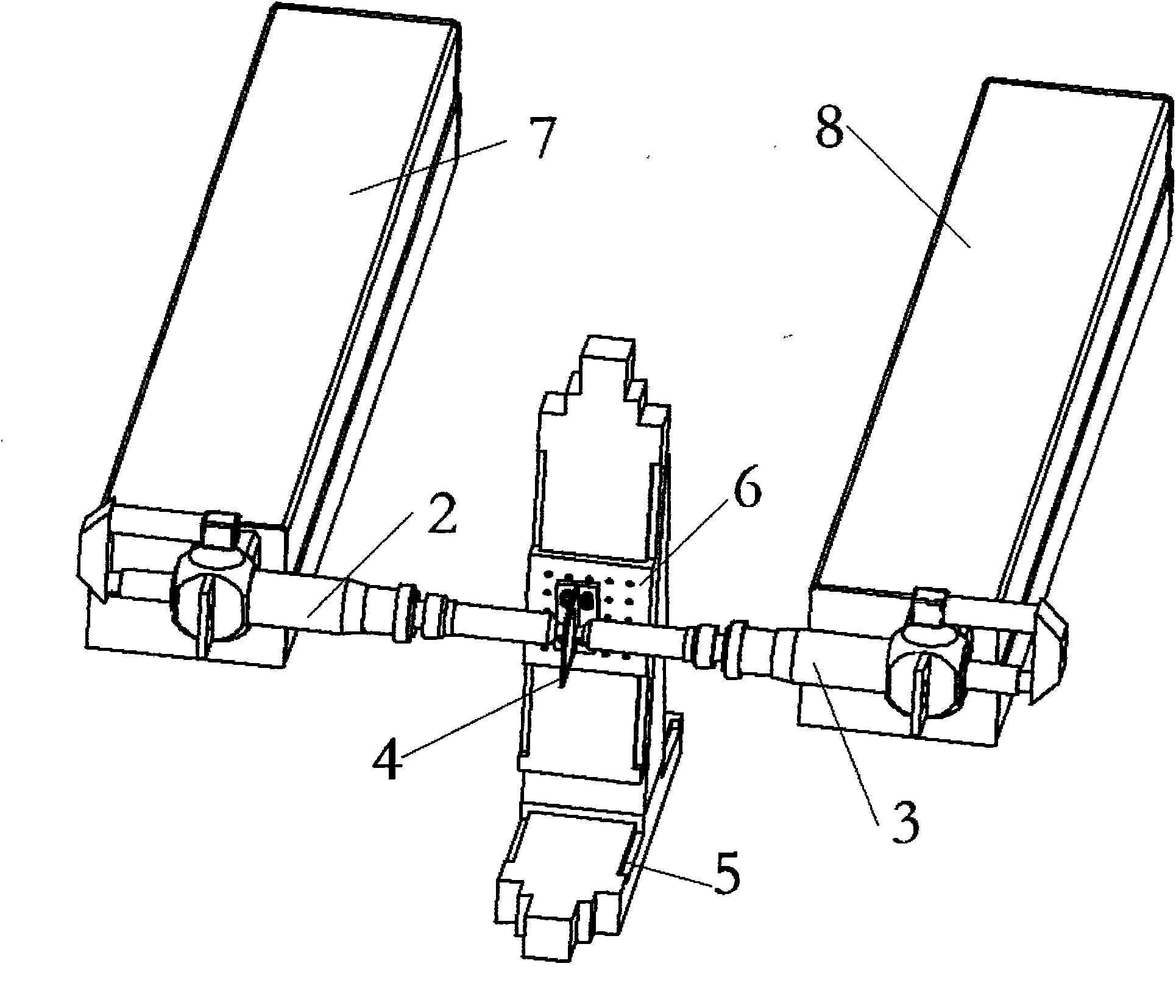
[0036] Example 1: Such as Figure 5 As shown, a laser double-sided synchronous processing system has a middle displacement worktable 5, a left laser processing machine 7, a right laser processing machine 8, and the middle displacement worktables 5 and 6 are X and Y moving worktables perpendicular to each other. , X mobile workbench and Y mobile workbench are connected by guide rails, lead screws, motors and control devices to form X and Y position moving devices. X mobile workbenches and Y mobile workbenches form a T-shaped structure. A clamping fixture is fixed on the upper Y movable table. The left laser processing machine 7 is installed on the left side of the middle table 5, the right laser processing machine 8 is installed on the right side of the middle working table 5, and the left and right laser processing machines are The laser beam outputs of 7 and 8 all point to the middle worktable, and the laser beam of the left laser processing machine 7 and the laser beam axis of...
Embodiment 2
[0043] The left and right laser processing machines 7 and 8 are powered by two independent laser power supplies. At the same time, two chillers are used to cool the left and right laser processing machines 7 and 8 to a certain temperature range to ensure the continuous and stable operation of the laser.
[0044] The light guide focusing system is directly connected to the laser output end of the laser through the light path transition device, and a CCD monitoring system coaxial with the laser light path is installed on the light guide focusing system;
[0045] The structure of CCD monitoring system is as Figure 7 It mainly includes a laser focusing lens 29, an imaging focusing lens 22, a reticle (scored glass sheet) 23, a camera 22, a display 21, etc., and the monitor 21 is connected to the camera 20 by a line. The monitored position of the processed workpiece 4 is generally near the laser focal point and centered on the laser focal point. The reflected visible light on the surfac...
Embodiment 3
[0050] Embodiment 3: A laser double-sided synchronous processing method, by using two laser generators, or using a beam splitter to split the laser beam of the same laser into two beams to obtain two laser beams, such as Figure 4 As shown, the energy ratio of the two beams can also be adjusted by using different dichroic prisms.
[0051] Use necessary devices, such as optical fiber transmission or mirror turning, and adjust the laser collimation to make the two laser beams face each other and on the same straight line;
[0052] Install the focusing lens on the two laser beam paths, and ensure that the focusing lens is perpendicular to the laser beam and the center of the beam coincides with the center of the focusing lens through a two-dimensional adjustment piece;
[0053] Through adjustment, the plane of the two-axis movement direction of the two-dimensional platform is strictly perpendicular to the direction of the laser beam or at a required tilt angle;
[0054] Install the toolin...
PUM
 Abstract
Description
Claims
Application Information
 - R&D
- Intellectual Property
- Life Sciences
- Materials
- Tech Scout
- Unparalleled Data Quality
- Higher Quality Content
- 60% Fewer Hallucinations
Browse by: Latest US Patents, China's latest patents, Technical Efficacy Thesaurus, Application Domain, Technology Topic, Popular Technical Reports.
© 2025 PatSnap. All rights reserved.Legal|Privacy policy|Modern Slavery Act Transparency Statement|Sitemap|About US| Contact US: help@patsnap.com


