
Three-step metal reducing method

A three-step method, metal technology, applied in iron oxide "three-step method" reduction of metal iron, metal oxide smelting reduction metal field, can solve the problem of low utilization rate of gas, poor bonding and discharging, pre-reduction Low speed and other problems, to achieve the effect of less impurities and non-metallic inclusions, good working conditions, and simple production links

Inactive Publication Date: 2010-03-10
贾会平
View PDF0 Cites 15 Cited by
  • Summary
  • Abstract
  • Description
  • Claims
  • Application Information

AI Technical Summary

Problems solved by technology

Since the pre-reduction device is often a shaft furnace and lump ore is used at the same time, the pre-reduction speed is low, which may easily cause poor bonding and discharging, and the utilization rate of the gas from the final reduction furnace is not high, the thermal efficiency is low, and the temperature of the gas discharged from the top of the shaft furnace is often Higher, the heating fuel of the final reduction furnace is mainly produced by the combustion of coal, and additional slag is produced in the final reduction furnace
[0004] The above one-step or typical two-step iron oxide smelting reduction has successfully solved the problem of not using coke in the production of molten iron, but only using non-coking coal. The two-step method also got rid of the adverse influence of the soft melting zone in blast furnace ironmaking, changing The gas permeability problem of the original blast furnace ironmaking, but the one-step method and the two-step method of smelting reduction have their inherent weaknesses

Method used


Image

  • Three-step metal reducing method
  • Three-step metal reducing method
  • Three-step metal reducing method

Examples


example 1

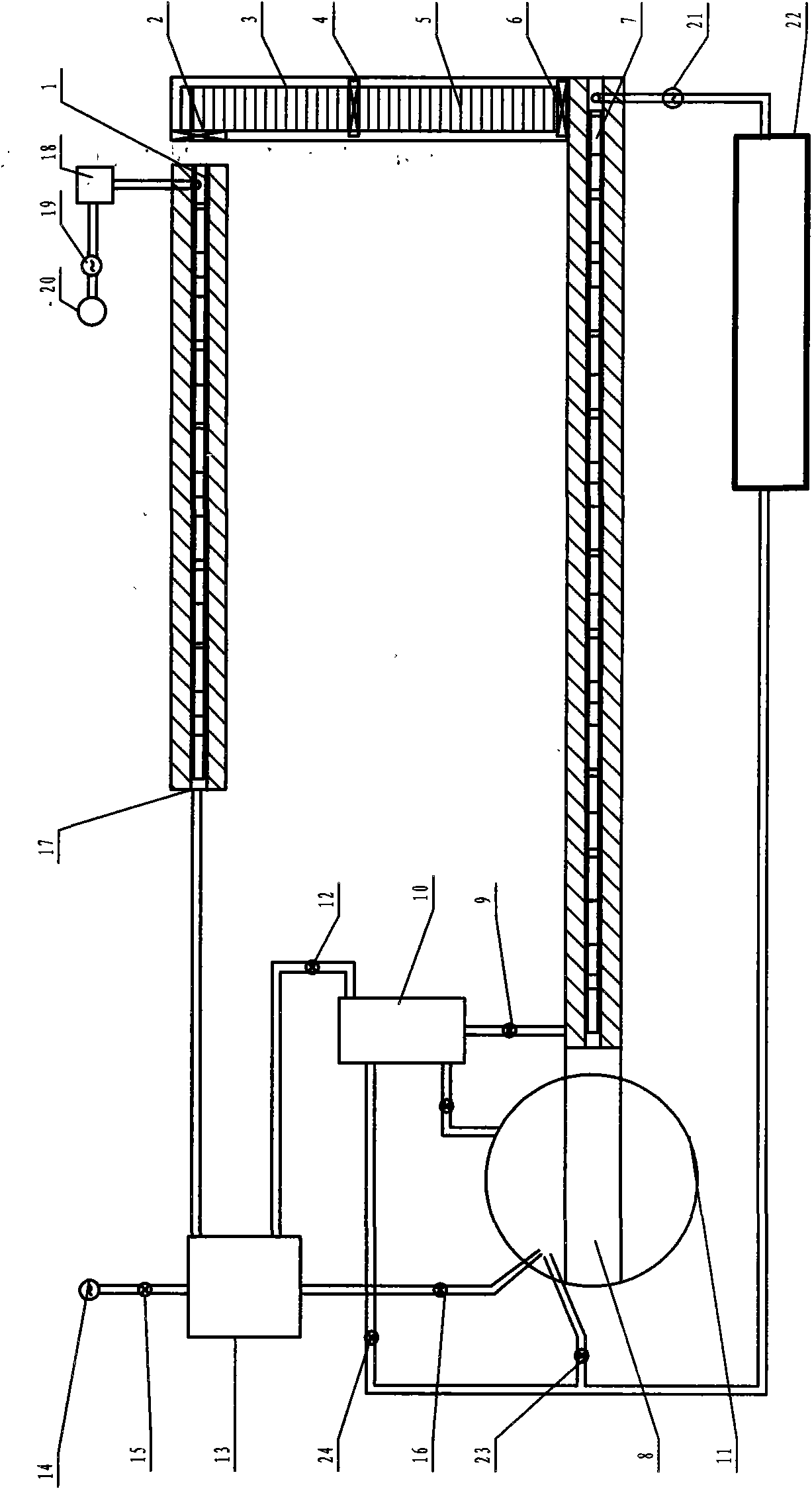
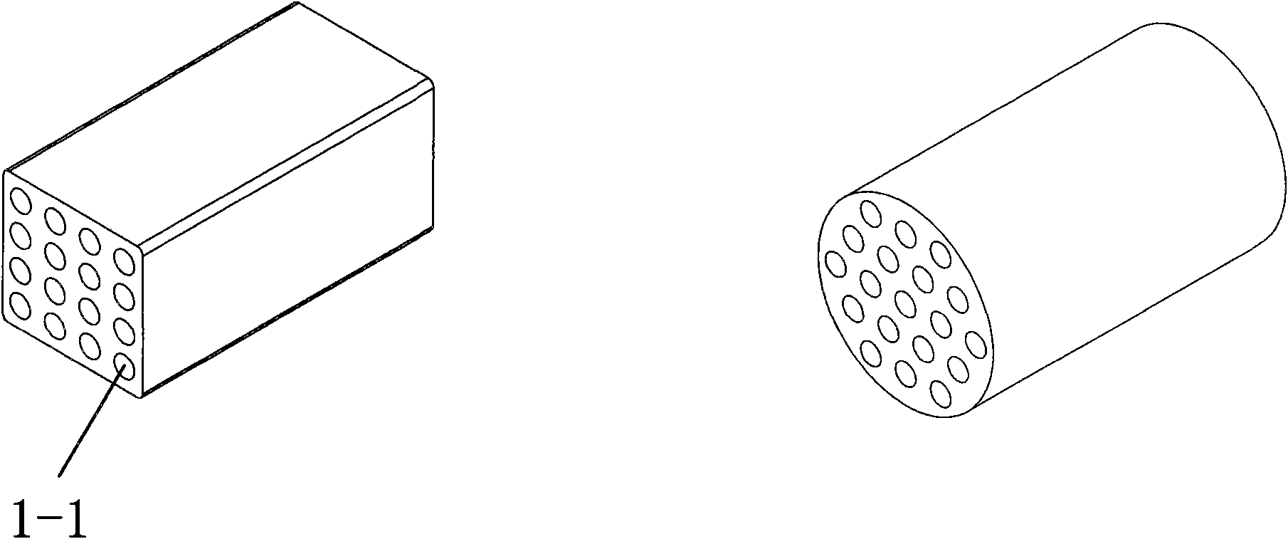
[0034]The reduction furnace can be a shaft furnace, a roller furnace, a pusher furnace, a bell furnace, a coke oven, etc. The reduction furnace is a roller furnace as an example. The molded object is placed on the bottom plate made of metal or non-metallic materials, the bottom plate is placed on the roller table, and the roller table moves the bottom plate forward through mechanical transmission. The roller shaft is made of non-metal or heat-resistant metal. The bottom plate and the roller shaft must have High-temperature strength, depending on the composition of the molded product, the base plate may not be used, and the molded product may be placed directly on the roller table. The roller table furnace adopts various seals to isolate air and oxygen. The shape of the molded product is as figure 2 Rectangular or cylindrical honeycomb shapes shown. Roller type reduction furnace device such as figure 1 As shown, the molded product is dried on the drying kiln 1 with low-tempe...

example 2

[0036] Such as Figure 6 As shown, it is similar to Example 1, except that a bath heating furnace 25 and a smelting furnace 26 are adjusted. After the high-temperature heat exchange device 10 is heat-exchanged, the precipitated gas through the valve 9 enters the molten iron molten pool from the bottom of the molten pool heating furnace 25 or the nozzle on the side of the furnace or the breathable refractory device, and enters the molten iron pool after being heated to a high temperature through the molten iron molten pool. In the associated reducing furnace 7, it is used as a heat carrier, reducing agent or protective gas to reduce the molded product, and the purpose of increasing the heating of the molten pool is to reduce the burden on the high-temperature heat exchange device 10, so that it can be processed at a lower temperature. The precipitated gas is preheated, and then the precipitated gas is heated by the molten pool heating furnace 25, so that the precipitated gas is...

example 3

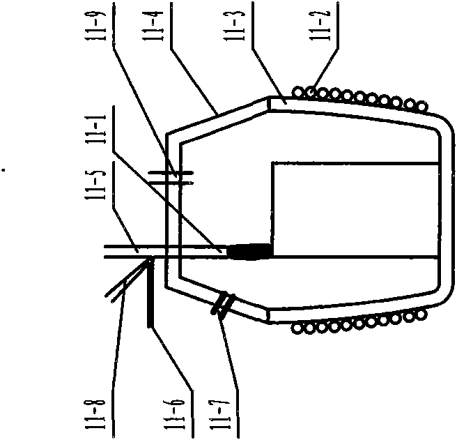
[0038] There are many external heating reduction furnaces using the three-step method, which can be shaft furnaces, roller furnaces, pusher furnaces, continuous heating furnaces, bell furnaces and coke ovens. In this example, an external heating reduction furnace similar to a bell furnace is used as a reduction furnace system. See Figure 7 , Figure 8 , using the molded product as figure 2As shown in the honeycomb molding, if its length is insufficient, it can be stacked with holes, or it can be block, spherical, rectangular or cylindrical molding, placed on the base 29-11 of the reduction furnace, and there is a refractory insulation material on the base 29-10, there are many connecting passages 29-12 at right angles on the refractory material as a whole, through the fan 29-15, the precipitated gas enters the right-angled connecting passage 29-12 through the honeycomb passage of the molding and then flows out along the metal heat-resistant material. (or non-metal refract...


PUM


Abstract

The invention relates to a three-step metal reducing method. A metal oxide and a certain amount of carbon, adhesive, CaO and water are prepared into a shaped substance, and the shaped substance is placed into a reduction device. The method comprises the following steps: firstly, pre-reducing the shaped substance under the condition of isolating air and oxygen; secondly, collecting separated gas produced during reducing in a reduction furnace of the first step, and cooling, purifying and pressurizing the separated gas; and finally, mixing and burning the separated gas and the heat exchanged airor oxygen rich gas, or mixing and burning the separated gas and pure oxygen, and finally reducing and melting a reduction furnace product in a final reduction furnace and removing the slag to producemolten iron or directly reduce molten steel. The method has the advantages of reasonable process flow, strong adaptability, flexible operation, energy conservation and good product quality, can be used for producing iron metals, and also can be used for reducing other oxygen-containing substances.

Description

technical field [0001] The invention belongs to the technical field of metallurgy and relates to a method for reducing metal by melting metal oxides, in particular to a method for reducing metallic iron by "three-step method" of iron oxides. Background technique [0002] The one-step smelting reduction of iron oxide was proposed at the beginning of the last century. It is to spray iron ore powder and coal powder directly onto the surface of the moving high-temperature and high-carbon iron molten pool, and CO burns in the upper part of the molten pool to generate a large amount of heat to meet System needs. In practical application, the one-step method has its limitations, mainly due to the following reasons: ①The large amount of heat generated by CO combustion cannot be effectively transferred to the reduction zone; ②The high-FeO slag severely corrodes the furnace lining; ③The heat energy utilization of the high-temperature gas exhausted from the reactor decreases. [0003]...

Claims


Application Information

Patent Timeline
Patent Type & Authority Applications(China)
IPC IPC(8): C21B15/00
Inventor 贾会平
Owner 贾会平
Learn More