Optical precision tracking detector based on double pyramidal rectangular pyramids

A tracking detector, optical precision technology, applied in the direction of instruments, measuring devices, measuring angles, etc., can solve the problem of not being able to balance the dynamic range and detection accuracy

Active Publication Date: 2010-03-17
INST OF OPTICS & ELECTRONICS - CHINESE ACAD OF SCI
View PDF0 Cites 15 Cited by
  • Summary
  • Abstract
  • Description
  • Claims
  • Application Information

AI Technical Summary

Problems solved by technology

However, the traditional optical precision tracking detectors based on pyramidal pyramids are limited by the processing technology of pyramidal pyramids. The diameter of the light spot irradiated on the pyramidal pyramids must be large to ensure sufficient detection accuracy, and the target surface

Method used


Image

  • Optical precision tracking detector based on double pyramidal rectangular pyramids
  • Optical precision tracking detector based on double pyramidal rectangular pyramids
  • Optical precision tracking detector based on double pyramidal rectangular pyramids

Examples


Embodiment Construction

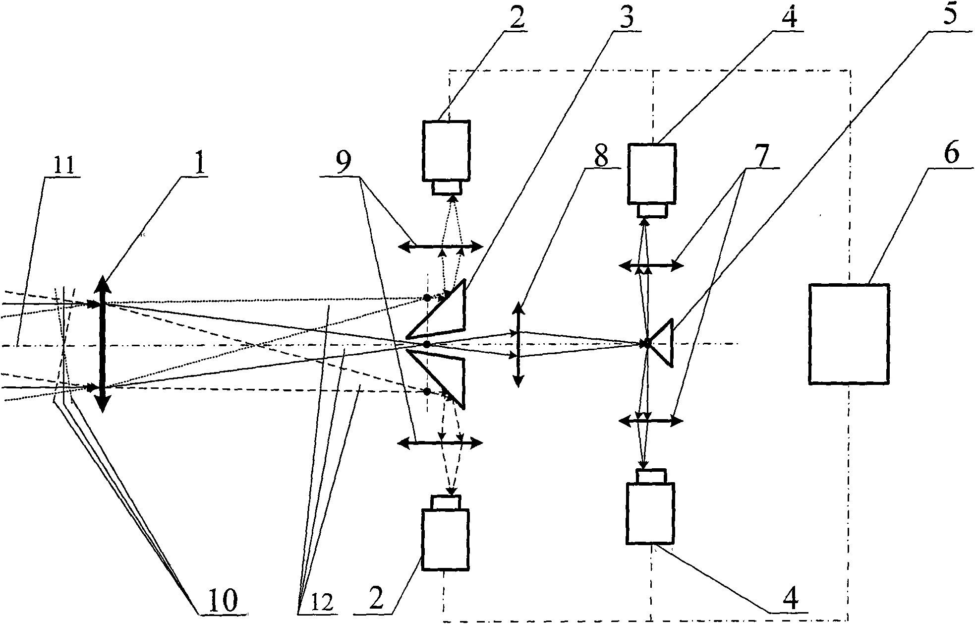
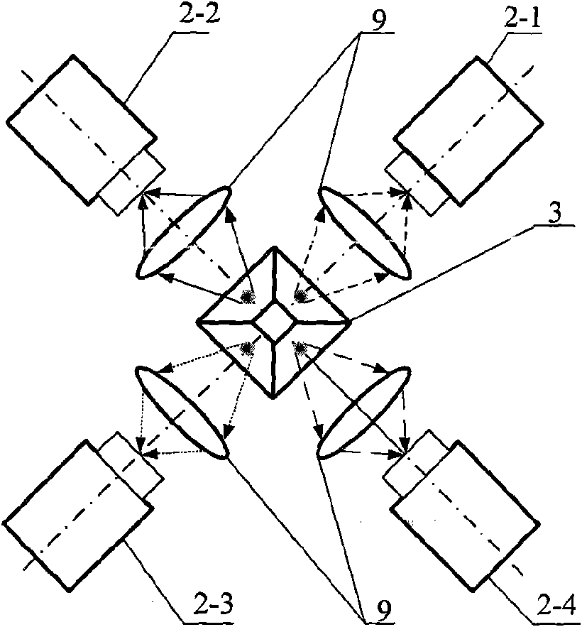
[0025] Such as figure 1 As shown, the present invention includes: an imaging lens 1, a dynamic range light intensity detector 2, a pyramidal pyramid 3 with a central opening, a precision light intensity detector 4, a precision pyramidal pyramid 5, an optical precision tracking detector processor 6, Precision matching lens 7, spot magnification lens 8, and dynamic range matching lens 9.

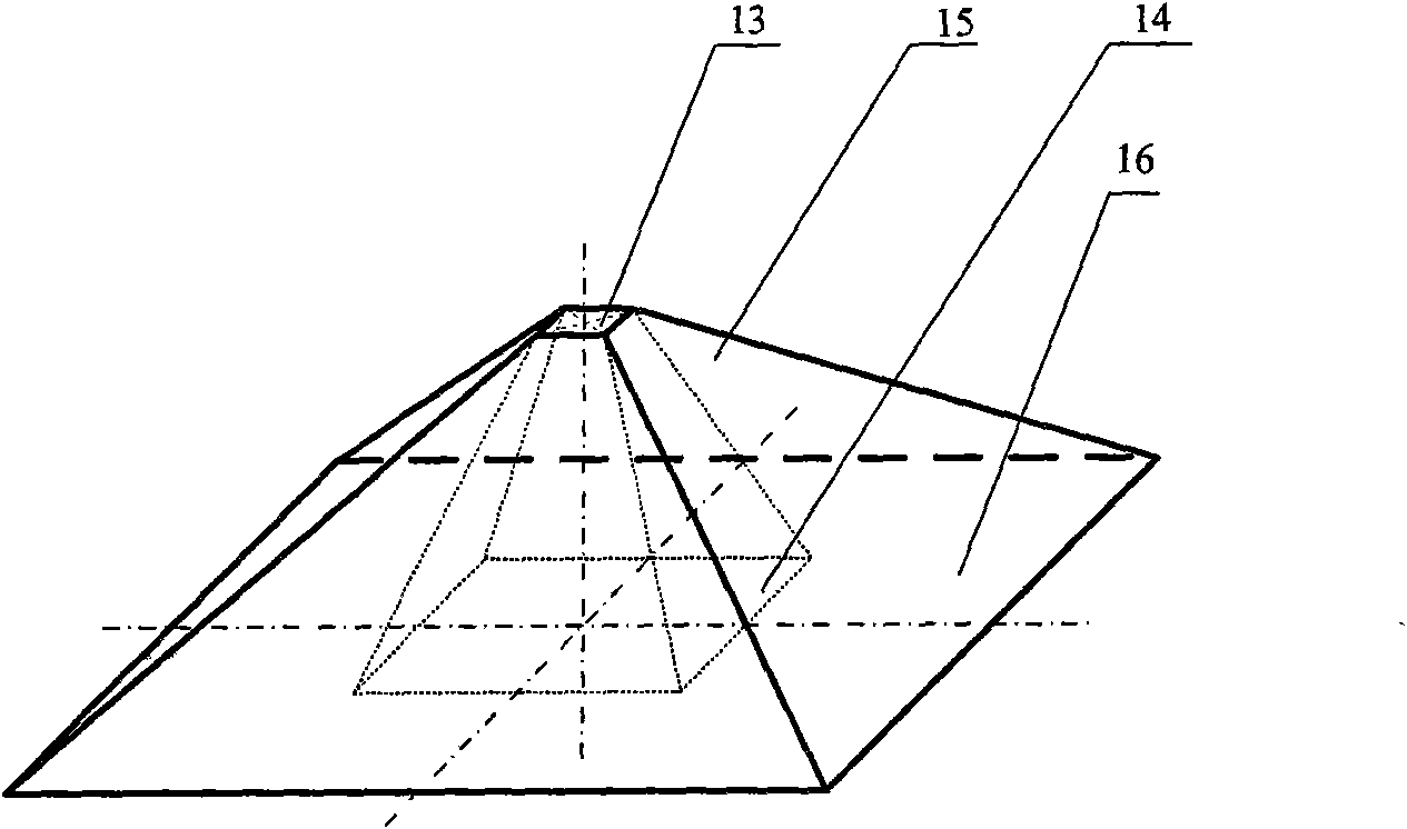
[0026] After the target wavefront 10 passes through the imaging lens 1 , its imaging beam 12 will deviate from the optical axis 12 of the imaging lens. The present invention just utilizes the characteristics of imaging light beam 12 and target wavefront 10 relations, places the pyramidal pyramid 3 of a central opening at the defocus plane place of imaging lens 1, the central axis of the pyramidal pyramid 3 of central opening and imaging The optical axes 12 of the lenses are coincident, and the upper plane 14 of the pyramidal pyramid with a hole in the center is placed at the defocus plane of ...


PUM


Abstract

The invention discloses an optical precision tracking detector based on a double pyramidal rectangular pyramids, which comprises an imaging lens, a pyramidal rectangular pyramid with an opening in thecenter thereof, a dynamic range matching lens, a precision matching lens, a light spot amplification lens, a dynamic range light intensity detector, a precision pyramidal rectangular pyramid and a precision light intensity detector, wherein the traditional optical precision tracking detector based on the pyramidal rectangular pyramid is added with the centrally-opened pyramidal rectangular pyramid, the dynamic range matching lens and the dynamic range light intensity detector in the hardware manner to increase the dynamic range of the detection in the oblique direction of wavefront tilt, andin the software manner, the nested four quadrant light spot centroid algorithm is used for calculating the centroid of the light spot so as to restore the tilt angle or the tilt direction of target wavefront. The light intensity detector of the optical precision tracking detector has flexible selectivity, high detection precision, large dynamic range of the detection in the oblique direction of wavefront tilt, simple algorithm for restoring the wavefront tilt and easily-realized process, thus providing conditions for the detection of weak light wavefront at high accuracy and high frame frequency.

Description

technical field [0001] The invention relates to an optical precision tracking detector based on a pyramidal pyramid, in particular to an optical precision tracking detector based on a pyramidal pyramid with the characteristics of large dynamic range and high precision, which can be applied in satellite-to-earth optical communication. Background technique [0002] Satellite-to-ground optical communication refers to the use of laser beams as carriers to establish optical communication links between satellites and the ground. Compared with the microwave communication commonly used at present, the satellite-ground optical communication has the advantages of large communication capacity, small system size and weight, strong confidentiality, less electromagnetic interference and wide frequency bandwidth. Therefore, many countries have invested huge financial, manpower and material resources in the research of star-to-earth optical communication. Among them, Japan used the ETS-VI ...

Claims


Application Information

Patent Timeline
IPC IPC(8): G01C1/00G01C9/00
Inventor 饶长辉马晓燠樊志华郑轶
Owner INST OF OPTICS & ELECTRONICS - CHINESE ACAD OF SCI
Why Eureka
Try Eureka